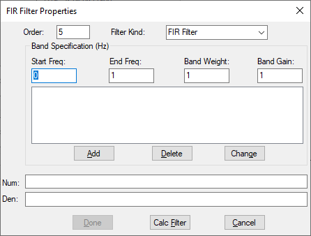
When you click the FIR Filter button in the Transfer Function Setup dialog box, the FIR Filter Setup dialog box is opened.
Describes the frequency bands magnitude response characteristics of the filter. The following rules must be observed when entering band specifications: (1) Frequencies are specified in hertz for discrete and continuous filters. (2) For discrete filters, the frequency specified must be lower than the Nyquist frequency. (3) For continuous filters, infinite frequency is indicated using the reserve word “inf.”
Band Gain: Defines the desired frequency response magnitude for each band.
Band Weight: Dictates the
relative amounts of error allowed for each band. Higher weight values of a
particular frequency band reflect higher sensitivity to error, where error is
perceived as the difference between the actual and desired filter response. At
least one band must have a weight of 1. For each of the other bands, you can use
a higher or lower weight depending on the relative error that can be
tolerated.
An equal weight of 1 on all bands indicates that the maximum
absolute error on all bands is the same. A weight of 10 on one band and a weight
of 1 on other bands imply that the former band has a maximum approximation error
that is ten times less than that of the other bands.
Start Freq and End Freq: Define the lower and upper cut-off frequencies for each band.
Filter Kind: Indicates the type of filter to be generated. Your choices are FIR, differentiator, and Hilbert transformation.
Order: Defines the filter order. Typically, higher orders yield better approximations.