Category: Toolbox > eDrives and Systems > eMotors > Other Tools > Tools
Inputs:
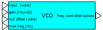
•Input: Input in volts. The output pulse width and frequency are determined by the magnitude of this input. This value is expected to be a positive non-zero quantity.
•Gain (Hz/volt): The oscillator frequency gain. The frequency of the output will be the product of the input voltage and the oscillator frequency gain, as long as it does not exceed the maximum frequency.
•Null Offset: The minimum value the input voltage must reach for the VCO to produce output. In other words, the VCO will ignore all input values that are less than the null offset value.
•Max Freq: Defines the maximum output frequency of the VCO. This will set the upper limit on the raw output frequency, which is the product of the input voltage and the gain.
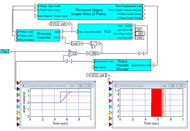
Description: The VCO block models a programmable voltage-controlled oscillator. It produces a series of clock pulses whose frequency is controlled by the input voltage.
Diagram name: VCO Stepper Control
Location: Examples > eDrives and Systems > eMotors > Steppers
This example illustrates a typical application where a stepper motor is used in feedback with an optical encoder. The output of the VCO is plotted in a plot block.