Creating the Port
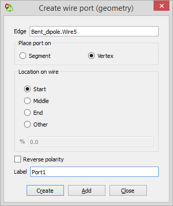
Define a wire port on the feed pin to excite the dipole. A voltage source will be added to this port.
See what's new in the latest release.
The Feko Getting Started Guide contains step-by-step instructions on how to get started with Feko.
The example is intended for users with no or little experience with CADFEKO. It makes use of a completed rectangular horn model to familiarise yourself with model creation in CADFEKO and viewing the simulated results in POSTFEKO.
The example is intended for users with no or little experience with CADFEKO. This example is not an example intended for simulation, but rather to familiarise yourself with model creation in CADFEKO.
The example considers the reflection coefficient and impedance of a microstrip patch antenna on a substrate modelled on an infinite substrate and then on a finite substrate.
The example considers the coupling between a typical monopole antenna and a loaded transmission line above a ground plane.
The example considers the transmission and reflection coefficients of a waveguide power divider.
The example considers the optimisation of the gain of a bent dipole in front of a plate.
Calculate and maximise the gain of a bent dipole in front of a plate. Optimise the dipole-plate separation distance and the dipole bend-angle.
Before starting this example, check if the topics discussed in this example are relevant to the intended application and experience level.
Before starting this example, ensure that the system satisfies the minimum requirements.
Create the model geometry using the CAD component, CADFEKO.
Launch CADFEKO to get started with creating a model.
Define variables to create a parametric model.
Create the plate at the origin with a vertical orientation.
Create the bent dipole using a polyline with three corners. Define the dipole on a new workplane to allow for easy translation.
Define a wire port on the feed pin to excite the dipole. A voltage source will be added to this port.
Add a voltage source to the port of the dipole.
Specify the frequency range of interest. For this example a single frequency point is used.
Apply symmetry to save computational resources.
Request far fields in the azimuth direction.
Add an optimisation search to maximise the maximum gain in the azimuth direction.
Specify the optimisation parameters. Choose from existing variables and specify their minimum and maximum values
Specify the goal focus, the operations to perform on the goal, and the goal objective.
Create a mesh suitable for the geometry and wavelength.
Launch the Solver to calculate the results.
Launch POSTFEKO from inside CADFEKO.
This example showed the construction, configuration and optimisation of a bent dipole in front of a plate.
The Feko Example Guide contains a collection of examples that teaches you Feko concepts and essentials.
Feko is a comprehensive electromagnetic solver with multiple solution methods that is used for electromagnetic field analyses involving 3D objects of arbitrary shapes.
CADFEKO is used to create and mesh the geometry or model mesh, specify the solution settings and calculation requests in a graphical environment.
POSTFEKO, the Feko post processor, is used to display the model (configuration and mesh), results on graphs and 3D views.
EDITFEKO is used to construct advanced models (both the geometry and solution requirements) using a high-level scripting language which includes loops and conditional statements.
One of the key features in Feko is that it includes a broad set of unique and hybridised solution methods. Effective use of Feko features requires an understanding of the available methods.
Feko offers state-of-the-art optimisation engines based on generic algorithm (GA) and other methods, which can be used to automatically optimise the design and determine the optimum solution.
The Feko utilities consist of PREFEKO, OPTFEKO, ADAPTFEKO, the Launcher utility, Updater and the crash reporter.
Feko writes all the results to an ASCII output file .out as well as a binary output file .bof for usage by POSTFEKO. Use the .out file to obtain additional information about the solution.
A large collection of application macros are available for CADFEKO and POSTFEKO.
CADFEKO and POSTFEKO have a powerful, fast, lightweight scripting language integrated into the application allowing you to create models, get hold of simulation results and model configuration information as well as manipulation of data and automate repetitive tasks.
Reference information is provided in the appendix.
The Feko Getting Started Guide contains step-by-step instructions on how to get started with Feko.
The example considers the optimisation of the gain of a bent dipole in front of a plate.
Create the model geometry using the CAD component, CADFEKO.
Define a wire port on the feed pin to excite the dipole. A voltage source will be added to this port.
Define a wire port on the feed pin to excite the dipole. A voltage source will be added to this port.

© 2022 Altair Engineering, Inc. All Rights Reserved.