A0 Card
The A0 card defines a linearly polarised incident plane wave.
On the Source/Load tab, in the Ideal
sources group, click the ![]() Plane wave
icon.
Plane wave
icon.
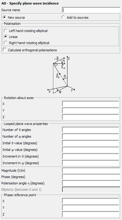
Figure 1. The A0 - Specify plane wave incidence dialog.
Parameters:
- New source
- A new excitation is defined which replaces all previously defined excitations.
- Add to sources
- A new excitation is defined which is added to the previously defined excitations.
- Polarisation
- This group sets the behaviour of the polarisation vector. If either the Left hand rotating elliptical or Right hand rotating elliptical is selected, the Ellipticity must be specified.
- Rotation about axis
- The rotation of the plane wave about the X axis, Y axis and Z axis.
- Number of angles
- If more than one direction of incidence is to be examined, then this parameter indicates the number of incident angles in the direction. If this field is left empty or set to 0, a value of 1 will be used.
- Number of angles
- If more than one direction of incidence is to be examined, then this parameter indicates the number of incident angles in the direction. If this field is left empty or set to 0, a value of 1 will be used.
- Magnitude
- Magnitude of the field strength of the incident field in .
- Phase
- Phase of the field strength of the incident field in degrees.
- Initial value:
- Angle of incidence of the plane wave in degrees.
- Initial value
- Angle of incidence of the plane wave in degrees.
- Polarisation angle
- It is the angle, in a right-handed sense when viewing in the incident direction from - to . See the card image in Figure 1.
- Increment in
- If more than one direction of incidence is to be examined, is incremented by this value for each new angle of incidence.
- Increment in
- If more than one direction of incidence is to be examined, is incremented by this value for each new angle of incidence.
- Ellipticity
- This field is only applicable when either the Left hand rotating elliptical or Right hand rotating elliptical is selected under Polarisation and gives the ellipticity of the rotating polarisation. It must be larger than 0 (linear polarisation) and smaller or equal to 1 (circular polarisation).
- Phase reference point
- The phase reference point for plane waves is set to the global origin by default. By modifying the phase reference, the simulation will zero the incident plane wave phase to the specified position.
The direction of incidence is specified by the incidence angles and . The polarisation angle (measured from the negative of the spherical coordinate system unit vector ) and the field strength vector are defined as indicated in Figure 1.
The electric field strength of the incident field is then given by
For linear polarisation, ellipticity is 0; for right hand rotating, ellipticity is equal to the value in the Ellipticity field; for left hand rotating, ellipticity is the negative of the value in the Ellipticity field. The incident magnetic field is given by
Note that the incident power density (which is required, for example, for RCS computations) is given by
If an A0 card with either Number of angles or Number of angles larger than 1 is read, all the following control cards up to, but excluding, the next Ax, FR or EN card will be read into a buffer. All these cards are then processed in a loop, over all the different angles of incidence.
If for example, the monostatic radar cross section is to be calculated for =90° and 0°≤ ≤180°, the following command is used:
A0: 0 : 0 : 181 : 1.0 : 0 :  :  : 0.0 : 0.0 : 0.1
FF: 2
EN
In this demonstration file, the FF card is read into the buffer and processed 181 times. Through the use of the parameter Fields calculated only in incident direction in the FF card the far field is calculated in the direction of the incident wave.
If more than one direction of incidence is to be examined, the right hand side of the linear equation system is changed, but the matrix remains unchanged. Thus it makes sense, by using the CG card, to use Gauss elimination (default if a CG card is not used) which performs a LU-decomposition of the matrix. When the direction of incidence is varied, then only the relatively fast backward substitution has to be performed.