Defining a Cable Path

A cable path is a defined route along which cables are installed and specified as a series of straight lines.

Note: A cable path may not consist of overlapping sections.


Figure 1. To create this cable path, five separate cable paths need to be defined namely: AB, BC, CD, EC and FB.
  1. On the Cables tab, in the Definitions group, click the  Cable path icon.
  2. Define the cable path using one of the following methods:
    • To specify the corner points, use point entry or add the U, V or N values directly for each point.
    • To import the points from a ASCII text file, click the Import points button.
      1. Under Source file, click ASCII text file.
      2. Under Source file, in the Filename field, browse to the file.
      3. Under Delimiter, click the relevant delimiter for your ASCII file.
    • To import the points from a NASTRAN file, click the Import points button.
      1. Under Source file, in the Filename field, browse to the file.
      2. Under Settings, in the Scale factor to metres field, modify the value to scale the cable path.
      3. Under Settings, in the NASTRAN segment ID field, enter the id of the segment to import.
      Note: Points imported from a NASTRAN file are assumed to be in metres.
  3. View the cable path in the 3D view.
    1. Select the Construct tab in the model tree.
    Cable paths are displayed as dotted-blue lines in the 3D view.


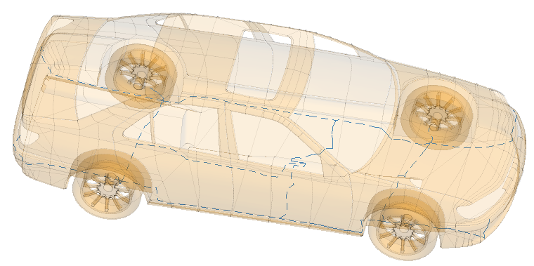
    Figure 2. Cable paths are visible in the 3D view when the Construct tab is selected. The cable paths are indicated by dotted-blue lines.
  4. In the Label field, add a unique label for the cable path.
  5. Click the Create button to create the cable path and close the dialog.