Specifying the FDTD Boundary Conditions
The boundary conditions define the volume solved by the finite difference time domain (FDTD) solver.
-
On the Solve/Run tab, in the
Solution settings group, click the
 FDTD boundary conditions icon.

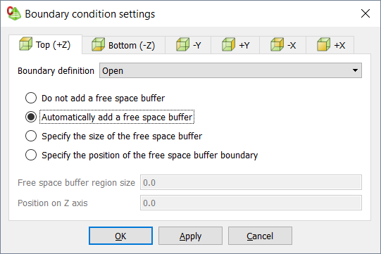
Figure 1. The Boundary condition settings dialog (Top (+Z) tab). - On the Boundary condition settings dialog, click the Top (+Z) tab to specify the boundary in the positive Z axis.
-
Specify the boundary definition by selecting one of the following from the
Boundary definition
drop-down list:
- To specify an open radiating boundary, implemented as a convolutional perfectly matched layer (CPML), select Open.
- To specify a PEC boundary that allows efficient simulation of infinitely large electrically conducting planes, select PEC.
- To specify a PMC boundary that allows efficient simulation of infinitely large magnetically conducting planes, select PMC.
-
Enlarge a volume by adding a free space buffer1 by selecting one of the following:
- If no free space buffer is required, select Do not add a free space buffer.
- To automatically add a free space buffer (perpendicular to the specific face), select Automatically add a free space buffer.
- To specify the size of the free space buffer to be added to the
specified face, select Specify the size of the free space
buffer.
- In the Free space buffer region size field, enter a value.
- To specify the position of the free space buffer on the respective axis,
select Specify the position of the free space buffer
boundary.
- In the Position on the Z axis field, enter a value.
- Repeat Step 2 to Step 4 for the remaining five faces of the boundary.
-
Click OK to define the boundary condition and to
close the dialog.
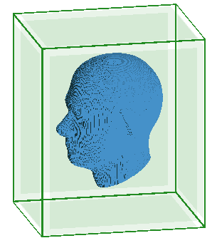
Note: A free space boundary condition is only displayed in the 3D view when the Configuration tab is selected.

Figure 2. An example of the display for six free space boundary conditions.
1 The buffer is the space
between the bounding box of the model and the position of the FDTD
boundary.