Define Symmetry
Define a symmetry plane on a part.
- The symmetry plane must be orthogonal to the draw direction of the model or FE mesh.
- The symmetry plane must be orthogonal or parallel to any existing symmetry planes in the model or FE mesh.
- If the draw direction is not defined in the model or FE mesh, the sofware automatically defines the draw direction as orthogonal to the symmetry planes.
- If your model or FE mesh requires symmetry planes, define the symmetry planes first, then modify the draw direction as required. When modifying the draw direction, the options that are valid are available in the microdialog. Invalid options are grayed out.
-
On the Feasibility tab, Orient
icon, click the Add/Edit Symmetry Plane tool.

-
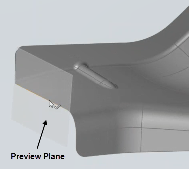
On the model or FE mesh, select an edge on a plane. The selected edge must be
on a plane and the plane must be orthogonal to the draw direction if the draw
direction is defined.
A preview of the symmetry plane is displayed if the selection is valid.