Single Action Draw Simulation with Top Pad and Drawbead
Learn how to perform a single action draw forming process that is set up with automatic tooling and positioning and is customized with added tools.
Open the Model
-
In the Open File dialog, navigate to the file in the
tutorials folder in the installation directory in
Program Files\Altair\2022\InspireForm2022\tutorials\s_rail.x_t.
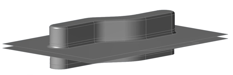
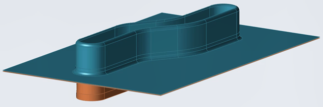
The model should look something like this:
Define the Blank and Material
-
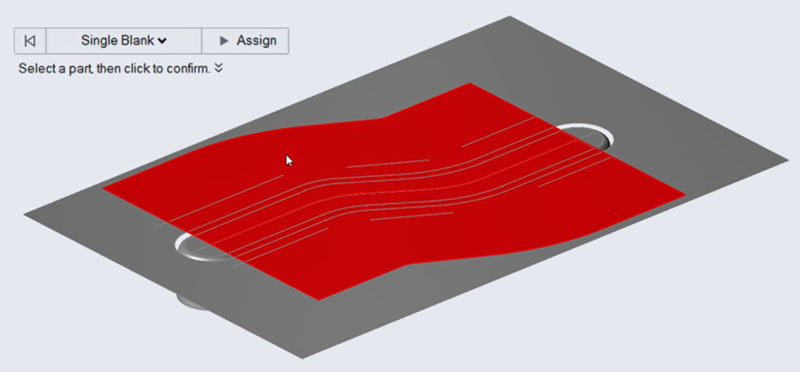
On the Tryout tab, click the Blank icon.

-
On the model, select the blank.
Note: To easily see the blank in the die set, you can hide parts that are blocking the view of the die. To hide a part, select it, right-click, then select Hide. Once you define the blank, unhide the parts.The blank turns red indicating your selection.
-
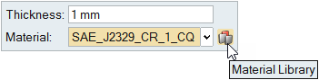
After assigning the blank, in the microdialog that appears, click the ellipses
button to access the Material Library.
-
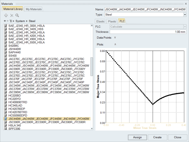
Click Assign, then Close.
Set Up the Single Action Draw Operation
-
From the Tryout tab, select the Add
 operation icon.
-
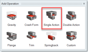
From the Add Operation window, select Single
Action.
 The Single Action operation icon appears on the Tryout tab.
 -
To automatically configure the toolset in your model, on the Single Action
operation you just added, click
 .
.

-
In the guide bar, the Build tools option is selected by
default. To confirm, click Auto configure.
The Build tools option automatically identifies the required tools for the operation, which includes a top die, bottom die, and bottom binder. The option also automatically configures the tool set.Note: An additional option to Auto Position the tools is available in the and is set by default.
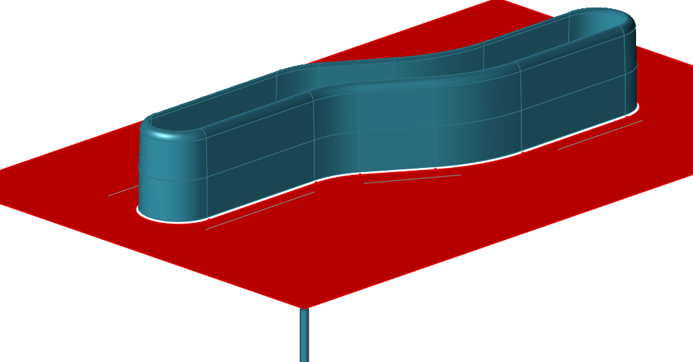
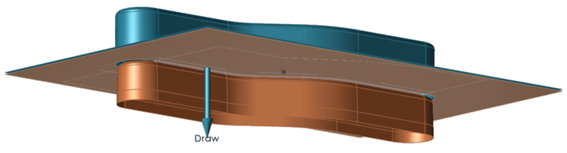 Figure 1. Model Setup for Single Action Draw
 -
To preview the forming action of the tryout, on the Single Action icon, click
Edit Action
 .
.
 An animation of the forming operation is generated for the model.
Add Tools to the Single Action Draw Operation
-
From the Tryout tab, select the Single Action operation
you just added.
-
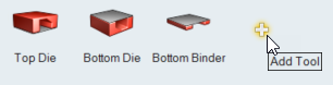
Next to the default tools that appear, click the Add
Tool button.
-
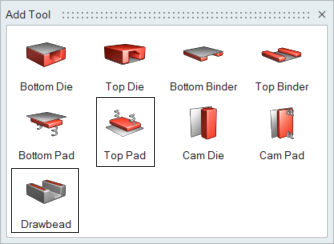
From the Add Tool dialog that appears, select the Top
Pad and Drawbead tools.
 The tools are added to the operation for you to configure. A user symbol
 is displayed indicating that a modification has
been made to the default tool set.
is displayed indicating that a modification has
been made to the default tool set.
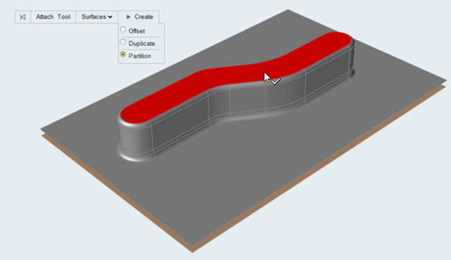
Configure the Top Pad
-
On the ribbon, select the Top Pad that you added to the
single-action-draw operation.

-
On the model, select the surface to designate as the top pad.
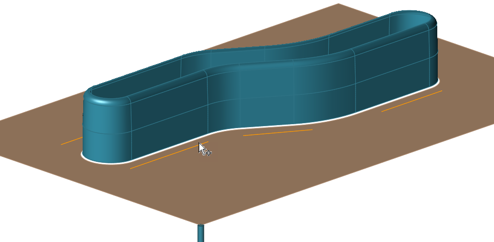
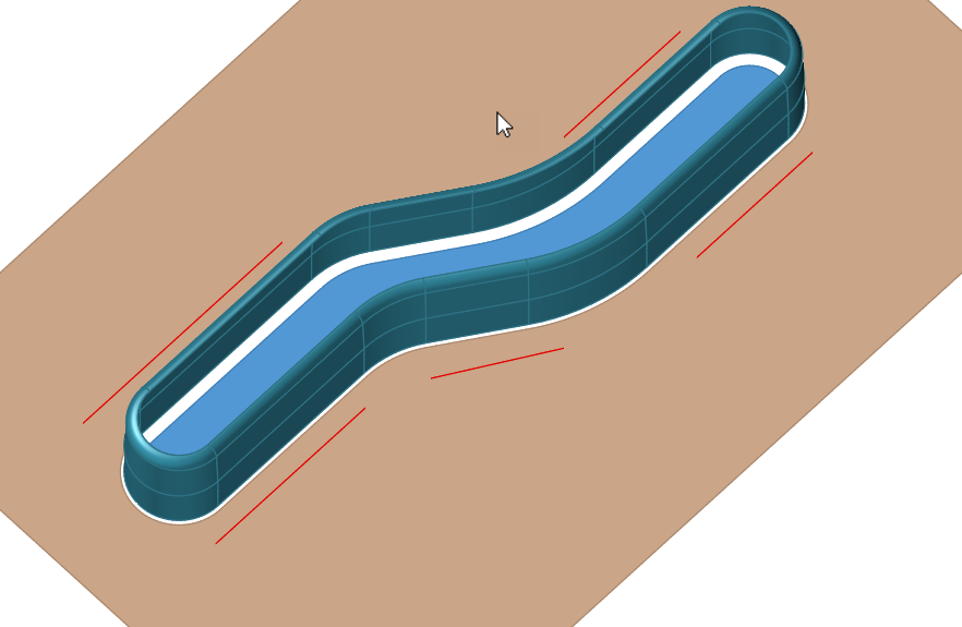
Configure the Drawbead
-
Select the Drawbead that you added to the Single Action
Draw operation.

-
On the model, select the bottom binder as the tool where you want to attach the
drawbead.
-
Select the lines where you want to create the drawbead.
Position the Die in the Forming Operation
 lets you preview the die set between the open and closed
states. The position of the die set can be defined automatically or manually.
lets you preview the die set between the open and closed
states. The position of the die set can be defined automatically or manually. -
On the ribbon, hover over the Single Action draw operation that you've added to
your analysis.

-
Click the Edit Position
arrow.
Run the Simulation
-
From the Tryout tab, Run tools, click Run Analysis
 .
.
-
In the Run Analysis dialog, type in a name, and click
Run.
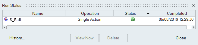
Note: By default, the run name is the model name, and is saved in the run history directory that is specified in the Preferences.The Run Status dialog shows the progress of the simulation. A green check mark indicates that the run is completed.
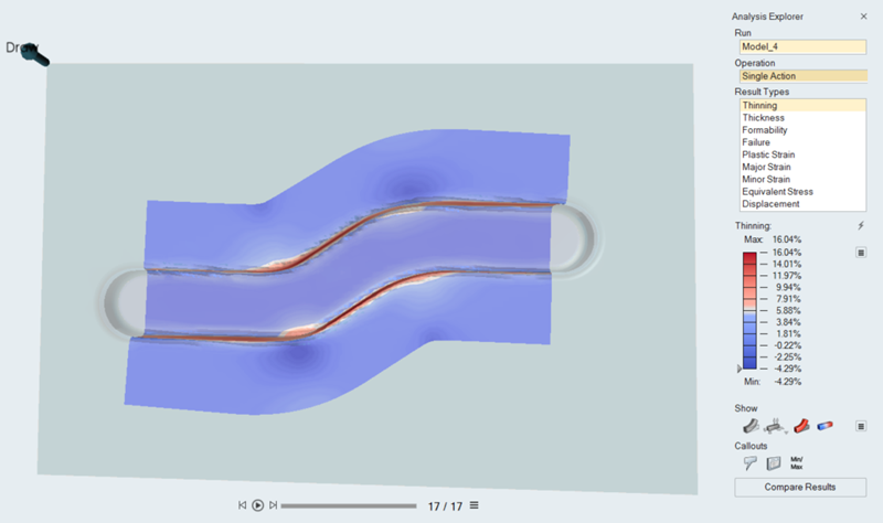
Review the Simulation Results
The Analysis Explorer lets you choose a variety of results to review. An animation for each result type is included. By default, the results for thinning are displayed on the formed part.
-
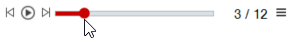
View the animation of the forming results by adjusting the slider that is
located at the bottom of the modeling window:
- To see what areas on your model are under the greatest thinning, click
and move the slider.
- To view the animation of the results, click the play button:

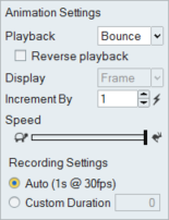
- To adjust the animation settings, click the edit button:
From the Animations Settings dialog, choose options for playback and display. To adjust the animation speed, move the slider to the right to increase or left to decrease the speed.
- To see what areas on your model are under the greatest thinning, click
and move the slider.
- To view additional results, from the Analysis Exporer, select a Run, Operation, and Result Type.