AcuLiftDrag
Extract the coefficient of lift and the coefficient of drag for one or more surfaces.
Syntax
acuLiftDrag [options]
Type
AcuSolve Post-Processing Program
Description
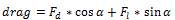
AcuLiftDrag is a post-processing utility that uses the AcuSolve database of surface integrated traction forces to compute the normalized lift and drag coefficients for one or more surfaces within the solution database.
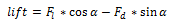
Where,  is the
force in the cardinal direction perpendicular to the inflow at zero angle of attack,
is the
force in the cardinal direction perpendicular to the inflow at zero angle of attack,
 is the force in the cardinal direction parallel to the inflow at zero angle of
attack and
is the force in the cardinal direction parallel to the inflow at zero angle of
attack and  is the
angle of attack in degrees of the surface in question.
is the
angle of attack in degrees of the surface in question.
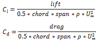
Where, the chord and span are defined by the wing_chord flag and
wing_span flag. These quantities are arbitrarily used to
define the total surface area of the body in question. Lastly,  is the
fluid density and
is the
fluid density and  is the
freestream velocity, defined by density and reference_velocity,
respectively.
is the
freestream velocity, defined by density and reference_velocity,
respectively.
In the following, the full name of each option is followed by its abbreviated name and its type. For a general description of option specifications, see Command Line Options and Configuration Files. See below for more individual option details:
- help or h (boolean)
- If set, the program prints a usage message and exits. The usage message includes all available options, their current values, and the place where each option is set.
- problem or pb (string)
- The name of the problem is specified via this option. This name is used to generate input file names and extracted surface file names.
- working_directory or dir (string)
- All internal files are stored in this directory. This directory does not need to be on the same file system as the user-supplied input files.
- run_id or run (integer)
- Number of the run in which the translation is requested. If run_id is set to 0, the last run in the working directory is assumed.
- surface_integral_output_sets or osis (string)
- Comma-separated list of surface_outputs to sum (support Unix style wildcard expressions). These are the user-given names specified as the user-given name of the SURFACE_OUTPUT commands in the input file. If surface_integral_output_sets is set to _all, all output sets are included into the force computation.
- wing_chord or chord (real)
- This option specifies the reference chord of the surface in question. If the term chord does not apply to the simulation, this option can be considered one dimension of the frontal area. The value is used to compute the reference area with chord*span, which is then used to normalize the force values into force coefficients.
- wing_span or span (real)
- This option specifies the reference span of the surface in question. If the term span does not apply to the simulation, this option can be considered one dimension of the frontal area. The value is used to compute the reference area with chord*span, which is then used to normalize the force values into force coefficients.
- angle_of_attack or aoa (real)
- This option specifies the angle of attack of the incoming fluid or surface in question. The value is used to decompose the cartesian traction vector quantities into fluid aligned lift and drag components.
- lift_direction or lift_dir (enumerated)
- This option specifies the direction of lift at zero angle of attack. You can specify values of x, y, or z referring to the cartesian coordinate system associated with the inflow direction.
- drag_direction or drag_dir (enumerated)
- This option specifies the direction of drag at zero angle of attack. You can specify values of x, y, or z referring to the cartesian coordinate system associated with the inflow direction.
- reference_density or ref_rho (real)
- This option specifies the reference density used to normalize the force values into force coefficients.
- reference_velocity or ref_vel (real)
- This option specifies the reference velocity used to normalize the force values into force coefficients. It should be specified as the magnitude of the inflow velocity.
- x_variable or x_vars (enumerated)
- This option specifies the x axis variable for the exported data: step, time.
- query or q (boolean)
- If this option is set to TRUE, the application will run in query mode. Query mode will simply print a list of surfaces that are available for force computation. The list of surfaces is queried from the list of surface_output sets available in the solution database.
- verbose or v (integer)
- Set the verbose level for printing information to the screen. Each higher verbose level prints more information. If verbose is set to 0 (or less), only warning and error messages are printed. If verbose is set to 1, basic processing information is printed in addition to warning and error messages. This level is recommended. verbose levels greater than 1 provide information useful only for debugging.
Examples
acuLiftDrag -osis "airfoil surface" -reference_velocity 14.5387 -wing_chord 1.0 -wing_span 50.0acuLiftDrag.pb=airfoil
acuLiftDrag.osis="airfoil surface"
acuLiftDrag.density=1.0
acuLiftDrag.wing_span=50
acuLiftDrag.aoa=0
acuLiftDrag.reference_velocity=14.5387755102acuLiftDrag:
acuLiftDrag: Opening the AcuSolve solution data base
acuLiftDrag: Problem <airfoil> directory <ACUSIM.DIR> runId <1>
acuLiftDrag:
acuLiftDrag: Opened run id <1>
acuLiftDrag:
acuLiftDrag: Processing surface output variable: traction
acuLiftDrag: Processing surface output: airfoil surface
acuLiftDrag: Writing file: airfoil.liftDrag.dat
acuLiftDrag:
acuLiftDrag: C_l - final: -0.00181443659229
acuLiftDrag: C_l - min: -0.0247666844194
acuLiftDrag: C_l - max: 0.016792946081
acuLiftDrag: C_l - ave: 0.000865548912408
acuLiftDrag: C_l'- rms: 8.97872604896e-159
acuLiftDrag:
acuLiftDrag: C_d - final: 0.00599087791896
acuLiftDrag: C_d - min: 0.00575298069594
acuLiftDrag: C_d - max: 0.515670407393
acuLiftDrag: C_d - ave: 0.011099596032
acuLiftDrag: C_d'- rms: 0.0381130336459
acuLiftDrag:
acuLiftDrag: Total elapsed time <0.7324> seconds
acuLiftDrag:The above example produces a single output file containing the simulated series of lift and drag coefficients called airfoil.lifDrag.dat.
The file contains the following columns:
timestep lift coefficient drag coefficient
100 -2.5207876546848220e-03 6.0041848600869774e-03
For a steady state simulation, only the last value is likely of interest to you, as it would be the converged solution for a Reynolds Averaged Navier-Stokes simulation. For a transient simulation the entire file may be useful to you, as this represents the time dependent lift/drag coefficients as calculated by AcuSolve.
acuLiftDrag -q
acuLiftDrag:
acuLiftDrag:  Opening the AcuSolve solution data base
acuLiftDrag:  Problem <airfoil> directory <ACUSIM.DIR> runId <1>
acuLiftDrag:
acuLiftDrag:  Opened run id <1>
acuLiftDrag:
acuLiftDrag:  Surface output name:                    +z slip
acuLiftDrag:       Number of surface nodes:           0
acuLiftDrag:       Number of integrated output steps: 300
acuLiftDrag:  Surface output name:                    -z slip
acuLiftDrag:       Number of surface nodes:           0
acuLiftDrag:       Number of integrated output steps: 300
acuLiftDrag:  Surface output name:                    airfoil surface
acuLiftDrag:       Number of surface nodes:           2616
acuLiftDrag:       Number of integrated output steps: 300
acuLiftDrag:  Surface output name:                    farfield
acuLiftDrag:       Number of surface nodes:           84
acuLiftDrag:       Number of integrated output steps: 300