A2 Card
With this card a voltage source is placed at a node between two segments or between a segment and a triangle, ground plane or polygonal plate. It is mostly used to feed wires attached to plates.
On the Source/Load tab, in the Sources on
geometry group, click the ![]() Voltage source icon. From the ドロップダウンリスト, click the
Voltage source icon. From the ドロップダウンリスト, click the ![]() Voltage on vertex (A2) icon.
Voltage on vertex (A2) icon.
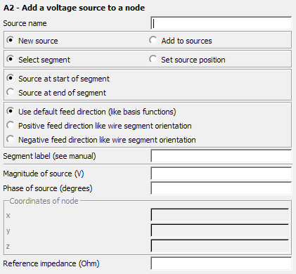
Figure 1. The A2 - Add a voltage source to a node dialog.
Parameters:
- New source
- A new source is defined that replaces all previously defined sources.
- Add to sources
- A new source is defined that is added to the previously defined sources.
- Select segment
- When this item is selected, then the Segment label field becomes active. Here one specifies the label of the segment that shall be fed (placed at either the start or end point as determined by the corresponding check box). The source has to be located at a node, either between two segments, or between a segment and a triangle, ground plane or polygonal plate. Only one segment with this label should be declared. If there is more than one segment with this label then only one node will be fed.
- Set source position
- If this check box is activated, the feed node is determined by specifying its Cartesian coordinates in the Coordinates of node group. These values are in m and may be scaled by the SF card. The source orientation is always consistent with the basis function defined over this node (see the information below under Use default feed direction).
- Source at start of segment
- This option is only available when selecting the feed segment by label. If set, it indicates that the feed location is at the start of the wire segment with a matching label.
- Source at end of segment
- This option is only available when selecting the feed segment by label. If set, it indicates that the feed location is at the end of the wire segment with a matching label.
- Use default feed direction
- This option is only available when selecting the feed segment by label. If set, it indicates that the positive feed direction is consistent with the basis function setup. For wire/surface junctions (UTD plates, infinite planes with the BO ground, or meshed triangle surfaces), this direction is away from the wire onto the surface. For wire connections between two segments, this direction is from the segment with the lower index to the segment with the higher index.
- Positive feed direction like wire segment orientation
- This option is only available when selecting the feed segment by label. If set, then the positive feed direction is like the orientation of the wire segment with the specified label.
- Negative feed direction like wire segment orientation
- This option is only available when selecting the feed segment by label. If set, the positive feed direction is opposite to the orientation of the wire segment with the specified label.
- Magnitude of source
- Magnitude of the voltage source in V.
- Phase of source
- Phase of the voltage source in degrees.
- Reference impedance (Ohm)
- 励振の基準インピーダンスは、Sパラメータの計算用に使用されると共に、得られた利得の計算に使用される基準インピーダンスです。この基準インピーダンスは、POSTFEKO内で反射係数を計算して表示するために使用されるデフォルトの基準インピーダンスでもあります。Sパラメータの計算でこの欄が空白または0の場合は、SPカードで指定された値が使用されます。得られた利得と反射係数の計算でこの欄が空白または0の場合は、50オームが想定されます。
There may not be more than two segments connected to the node for nodes between segments.
For nodes between a segment and a triangle, UTD plate or an
infinite plane only one segment is allowed to connect at the node.
Note: The vector
direction of the feed is the direction of the current flow through the node. The internal
electromagnetic force (EMF) of the impressed voltage is in the opposite
direction.