A6 Card
This card specifies excitation by an elementary magnetic Hertzian dipole.
On the Source/Load tab, in the Ideal sources
group, click the ![]() Magnetic dipole
(A6) icon.
Magnetic dipole
(A6) icon.
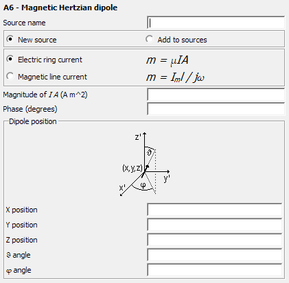
Figure 1. The A6 - Magnetic Hertzian dipole dialog.
Parameters:
- New source
- A new excitation is defined which replaces all previously defined excitations.
- Add to sources
- A new excitation is defined which is added to the previously defined excitations.
- Electric ring current
- Use the model of an electric ring current for the magnetic dipole (the moment where I is the loop current and A the enclosed surface area).
- Magnetic line current
- Use the model of an magnetic line current (the moment where Im is the magnetic line current and is the length of the dipole).
- Magnitude of I A (A m^2)
- The magnitude of the dipole. For the electric ring current it is in Am2. For the magnetic line current it is in Vm.
- Phase (degrees)
- Phase of the complex amplitude in degrees.
- X, Y, Z position
-
Coordinates of the position of the dipole in m. These values are optionally scaled by the SF card.
- angle
- The angle between the dipole and the Z 軸 in degrees.
- angle
-
The angle between the projection of the dipole onto the plane Z=0 and the X 軸 in degrees.
Feko, however, considers the properties of the medium in which the dipole is located, as well as the coupling of the dipole with surrounding structures or other sources (for example other magnetic dipoles in an array antenna), when calculating the power radiated by the Hertzian dipole.
Even though the two formulations, electric ring current and magnetic dipole, result in the same near and far fields, if the dipole moment m is the same, the radiated potentials are different.
The electric ring current model gives rise to a magnetic vector potential A while the magnetic dipole model results in an electric vector potential F as well as a magnetic scalar potential .