Specify the Source in the PRE File
With this option a waveguide port excitation by means of an impressed mode on a rectangular, circular, or coaxial waveguide, can be modelled.
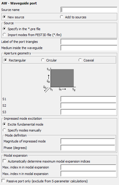
Figure 1. The AW - Waveguide port dialog.
Parameters:
- New source
- A new excitation is defined which replaces all previously defined excitations.
- Add to sources
- A new excitation is defined which is added to the previously defined excitations.
- Label of the port triangles
- Label of the triangular mesh elements in the mesh which represent the waveguide port. (If multiple solutions are defined in the same .pre file, then the usage of the waveguide ports with respect to the label(s) to which it/they are applied must be consistent for all solutions.)
- Medium inside the triangles
- The label of the medium inside the modelled waveguide.
- Rectangular
- A rectangular waveguide cross section is used, which is defined by three points S1, S2, and S3 as follows: S1 is an arbitrary corner point, and S2 and S3 are two corner points which define the waveguide sides (from S1 to S2) and (from S1 to S3). The direction in which the mode is launched is given by .
- Circular
- A circular waveguide cross section is used. The point S1 denotes the centre of the circular port, and the point S2 specifies the radius and start point for the angular dependency. A further point S3 must be perpendicular above the centre of the circular plate, so that the direction from S1 to S3 indicates the direction in which the waveguide modes are launched.
- Coaxial
- Here a feed of a coaxial waveguide with circular cross sections of both the inner and outer conductor can be specified. The point definitions are the same as for the circular waveguide, except that an additional point S4 must be defined between S1 and S2 which specifies the radius of the inner conductor.
- Excite fundamental mode
- Select this option to automatically excite the fundamental mode of the waveguide. When this option is selected, the mode type and its indices ( and ) cannot be specified since they are determined automatically.
- TE-mode
- If this option is checked, a mode (also referred to as ) is used as excitation. This option is only available when Excite fundamental mode has not been selected.
- TM-mode
- If this option is checked, a mode (also referred to as ) is used as excitation. This option is only available when Excite fundamental mode has not been selected.
- TEM-mode
- If this option is checked (only available for the coaxial waveguide since TEM modes don’t exist in rectangular/circular waveguides), a TEM mode is used as excitation. This option is only available when Excite fundamental mode has not been selected.
- Mode index m
- The index of the or mode which is impressed at the port. Note that for a rectangular waveguide the index m is related to the direction (for example from point S1 to S2). For a circular/coaxial waveguide, denotes the angular dependency. This option is only available when Excite fundamental mode has not been selected.
- Mode index n
- The index of the or mode which is impressed at the port. Note that for a rectangular waveguide the index is related to the direction (for example, from point S1 to S3). For a circular/coaxial waveguide, denotes the radial dependency. This option is only available when Excite fundamental mode has not been selected.
- Magnitude of impressed mode
- Absolute value of the complex amplitude of the impressed mode. For a TE-mode the unit is , for a TM-mode the unit is , for a TEM-mode the unit is . Note that an amplitude of zero can also be specified. In this case a waveguide port is acting purely as a passive port (for example, as waveguide termination), and no wave is launched.
- Phase (degrees)
- The phase of the impressed mode in degrees.
- Rotation angle (degrees)
- This option is available for circular and coaxial modes only and indicates the rotation angle in degrees by which a mode is rotated anti-clockwise with respect to the reference direction (point S2).
- Modal expansion
- At a waveguide port a specific mode is used as impressed excitation. However, due to discontinuities in the model, also higher order modes can result and will be propagating backwards through the port (applies to both active and passive ports). The maximum modal expansion indices taken into account during the calculation can be determined automatically by the kernel or specified manually. The included modes must be sufficient to capture the resulting field distribution of the problem. Note that the mesh across the waveguide port must be fine enough to represent the potential rapid field variation of included higher order modes. Also note that an increased number of higher order modes included in the model may have a significant impact on the run-time. If specified manually then the input values denote the maximum mode indices and which will be used to expand the backwards travelling waves. If determined automatically, then all propagating modes will be included, as well as evanescent modes that decay faster than at a tenth of a wavelength away from the waveguide port.
- Passive port only (exclude from S-parameter calculations)
- The waveguide port can be marked as passive only so that it will not be considered during S-parameter calculations. In this case the port is acting purely as a passive waveguide termination, and the coupling to and from this port will not be calculated.