LE Card
This card specifies complex series and parallel circuits applied to an edge between surface triangles.
On the Source/Load tab, in the Loads /
networks group, click the ![]() Load icon. From the ドロップダウンリスト, click the
Load icon. From the ドロップダウンリスト, click the ![]() Load edge (LE) icon.
Load edge (LE) icon.
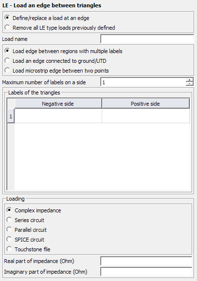
Figure 1. The LE - Load an edge between triangles dialog.

Figure 2. Application of the LE card.
Parameters:
- Define/replace a load at an edge
- Define a load with the following parameters.
- Remove all LE type loads previously defined
- This LE card does not define a load, but rather all previously defined LE loads are deleted. All the other input parameters of this card are ignored.
- Load name
- The name of the load.
- Load edge between regions with multiple labels
- The edge between different regions is loaded with a complex impedance. The following
parameters apply when this item is checked:
- Maximum number of labels on a side
- his indicates the maximum number of different labels used on either side of the load. Increasing this value will add rows to the table for the labels.
- Negative side
- The Labels of triangles on the one side of the load.
- Positive side
- The Labels of triangles on the other side of the load.
- Load an edge connected to ground/UTD
- Load the triangles with specified labels that are connected to a UTD surface or to a PEC ground plane (as specified with a BO
or GF card). The following parameters apply when this item is checked:
- Maximum number of labels on a side
- This indicates the maximum number of different labels used on either side of the load. Increasing this value will add rows to the table for the labels.
- Meshed surface represents positive feed side
- If selected, the Positive side of the Labels of triangles is connected to ground.
- Load microstrip edge between two points
- This is a special microstrip port load. The load is placed on all edges on the line
between two points (previously specified with DP cards) entered into the dialog. A GF
card with a conducting ground plane must be present. The following parameters apply when
this item is checked:
- Start point of edge
- The start point (not label) of the edge.
- End point of edge
- The end point (not label) of the edge.
- Meshed surface represents positive feed side
- If selected, the positive side of the microstrip edge between two points is connected to ground.
- Complex impedance
- The real and imaginary part of the complex impedance in .
- Series circuit
- The resistor value in , inductor value in Henry and the capacitor value in Farad to be added as a series circuit.
- Parallel circuit
- The resistor value in , inductor value in Henry and the capacitor value in Farad to be added as a parallel circuit.
- SPICE circuit
- Specify the name of a one-port SPICE circuit to define a load between two pins. Define the SPICE circuit using the SC card.
- Touchstone file
- Specify a one-port Touchstone file (.s1p,
.z1p, .y1p) to define a load.Note: If the load is added to a port that has a voltage source, the load is placed in series with the voltage source.
See also the AE card for the excitation of such an edge. As shown in the figure above, the edge can consist of several single edges between regions specified by labels. (See the AE card for a discussion on the allowed configurations.) Alternatively the edge can be along a connection between triangles and a polygonal plate or a PEC ground plane, or it can be a microstrip feed line port. The impedance Z applies to the complete edge (all the single edges in parallel). The LE card can be combined with the AE card to specify both an impedance and a voltage source over the edge.
Note that the edge between the triangles does not need to be straight. One may, for example, specify a resistive connection between two half cylinders.