LN Card
This card defines a complex load to any non-radiating network port that is not connected to geometry (that is any non-radiating network of the type Internal).
On the Source/Load tab, in the Loads /
networks group, click the ![]() Load icon. From the ドロップダウンリスト, click the
Load icon. From the ドロップダウンリスト, click the ![]() Load network (LN) icon.
Load network (LN) icon.
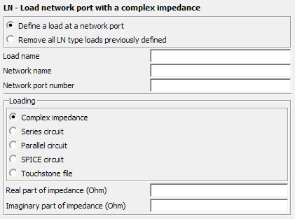
Figure 1. The LN - Load network port with a complex impedance dialog.
Parameters:
- Define a load at a network port
- Define a network load with the following parameters.
- Remove all LN type loads previously defined
- All previously defined LN type loads are removed. This replaces all network loads with open circuits. Note that setting the load impedance to zero creates a short circuit between the network terminals.
- Load name
- The name of the load.
- Network name
- The network or transmission line name, with the network port number, that uniquely identifies the connection terminals.
- Network port number
- The network port number, with the network or transmission line name, that uniquely identifies the connection terminals.
- Loading
-
- Complex impedance
- Define the real and imaginary parts of the complex impedance in Ohm using Real part of impedance (Ohm) and Imaginary part of impedance (Ohm) respectively.
- Series circuit
- The resistor value in Ohm, inductor value in Henry and the capacitor value in Farad to be added as a series circuit.
- Parallel circuit
- The resistor value in Ohm, inductor value in Henry and the capacitor value in Farad to be added as a parallel circuit.
- SPICE circuit
- Specify the name of a one-port SPICE circuit to define a load between two pins. Define the SPICE circuit using the SC card.
- Touchstone file
- Specify a one-port Touchstone file (.s1p,
.z1p, .y1p) to define a load.Note: If the load is added to a port that has a voltage source, the load is placed in series with the voltage source.
- Real part of impedance (Ohm)
- The real part of the complex impedance in .
- Imaginary part of impedance (Ohm)
- The imaginary part of the complex impedance in .