Triangles as Thin Isotropic Dielectric Sheet
This option defines a thin isotropic dielectric sheet (may consist of several layers).
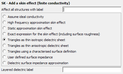
Figure 1. The SK - Add a skin effect (finite conductivity) dialog.
Parameters:
- Layered dielectric label
- Label of the layered dielectric medium which will be used (as specified in the DL card).
This option is practical only for triangular surfaces, and not for wires. The required parameters are d, , and as well as or so that and the complex dielectric constant . Usually either or is entered as zero, but it is possible to specify both (for example to approximate a specific frequency response). Feko will give a warning which may be ignored.
The triangles with the label Affect all structures with label exist in a certain environment ( , ), which is usually specified with the DI card. The surrounding medium is denoted by label “0” and by default contains the parameters of free space. It is also possible to place the triangles within a dielectric body — in this case the environment is specified by modifying the parameters of material “0” in the DI card. An additional condition is that the triangles should be geometrically thin, that is d must be small relative to the lateral dimensions. The mesh size is determined by the wavelength in the environment (that is in the medium , ). Therefore the layers must be thin relative to the wavelength in the environment.
When used with the MoM, the use of Triangles as thin isotropic dielectric sheet requires that the relations and are satisfied. For a single layer, the card consists of only one line. The surface impedance, as used by Feko, is then
For multiple layers the card requires one line per layer with the parameters of the first layer on the same line as the card name. The approximate surface impedances of the different layers are added to determine the effective surface impedance.
When used with PO, it is not required that the relations or are satisfied. In this case the order of the layers is also significant. The layer on the side that the triangle normal vector points to, is specified in the first line with the remaining layers following in sequence.