Track Model
A continuous track plug-in for tracked vehicles, such as bulldozers, excavators, robots, snowmobiles, and military vehicles.
Found in MotionView and MotionSolve, the track plug-in automatically assembles a continuous band of treads or track plates driven and suspended by two or more wheels, which can interact with soft-soil surface.
Definition
- Wheel
- Transfers the vehicle weight to the track.
- Sprockets/Sprocket-wheel
- Profiled wheel with teeth, or cogs, that mesh with a chain, track. Sprocket and its teeth are modeled as spheres, which contact with chain, track to transfer motion.
- Idler
- A wheel that is used to alter the path of the belt, chain, track, or to increase the wrap angle.
- Roller/Track Support Roller/Track Return Roller
- A small wheel used to prevent the catenary hang of the track and support the load of the track
- Tensioner
- A wheel that is used to set the right tension on the track chain which affects the maneuverability, power, efficiency, and life of the track.
- Pulley
- A wheel that is used to transfer power between two shafts in combination with a belt. It has a similar function to a sprocket for chains and tracks.
- Belt
- A continuous, flexible component that transfers power. In the track plug-in, sphere-to-sphere contact is used to transfer the power from a pulley to a belt.
- Chain
- A component that transfers power using multiple links. In the track plug-in, sphere-to-sphere contact is used to transfer power from a sprocket to a chain.
- Track
- A component that transfers power and distribute the loads from wheel to ground. In the track plug-in, sphere-to-sphere contact is used to transfer power from a sprocket to a track. Sphere-to-box contact is used to transfer power from a roller, wheel, idler, and tensioner to the track.
- Soft Soil
- Model provides the interaction between the track and soil and is based on the widely used Bekker, Janosi, and McKyes approaches.
Process
To build a track model successfully in MotionView, create a system of rolling elements, such as sprockets and wheels. The rolling elements are necessary for the track plug-in to identify the path of the track. Once the rolling elements are generated, the track itself can be built that wraps around the rolling elements. Additionally, specific track element updates can be performed after the track is built. Finally, the soft-soil model can be updated. With each track, a soft-soil model is generated automatically, but these models have default properties, and hence, an update might be necessary on the application. A detailed step-by-step instruction can be found in the tutorial .
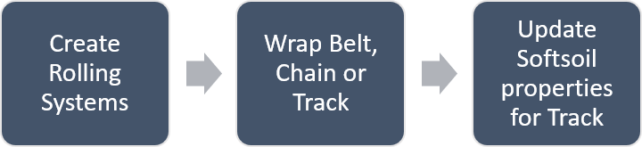
Figure 1. Track model process
Create Rolling System Dialog
Use this dialog to create sprocket, idler, roller, tensioner, wheel, and pulley rolling systems. You can use the Symmetric pair option to create rolling in a pair symmetric to the x-z plane. Rolling elements are usually built as a combination of primitive geometries glued together. However, you can also add CAD or H3D Graphics to the rolling system instead to increase the fidelity of the model. Mass and inertia for the rolling system are calculated based on the provided geometric dimensions or CAD Graphics. Alternatively, user-defined mass and inertia can be provided instead. The properties of the rolling system can be modified in the dataset under the rolling system after the system has been created.
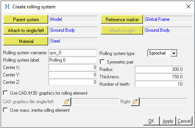
Figure 2. Create rolling system dialog
Wrap Rolling System Dialog
Use this dialog to wrap a track, chain, or belt on a rolling system. You can pick the Track/Chain or Belt option based on the type of wrapping. Track uses sphere-to-sphere contact between the sprocket and track and sphere-to-box contact for other entities and the track. Chain uses sphere-to-sphere contact for the sprocket and chain. The belt uses sphere-to-sphere contact between all entities and the belt. By default, track, chain, and belt are represented by a combination of primitive geometries. If necessary, you can use the CAD or H3D file of all entities for the track, chain, or belt instead. The CAD or H3D file is positioned at the mid-marker and can be repositioned using a dataset.
Start with entering to total number of “rolling entities” that are used within the track, chain, or belt. The user interface updates based on the number provided. Wrap the track, chain, or belt by picking the rolling elements in sequence in a clockwise direction. In other words, in a positive direction about Y-axis with respect to the local reference frame of the rolling system. All rolling systems should share the same frame of refence for wrapping.
The belt, chain, or track can be wrapped around the rolling elements such that the elements are either located inside or outside. Based on the wrapping, some rolling elements might not even touch the belt, chain, or track initially, but might come in contact with it during the course of the simulation.
The soil interaction can be turned off when not required in case of chain drives or simulation with particles from EDEM.
- Soft Soil
- Rigid Contact
By default, a soft soil model or Rigid contact is defined on the belt, chain, or track that represents the interaction of the system with the ground. Rigid Contact can be defined using Terrain graphics created from a soil terrain file or using the CAD geometry generated from external source.
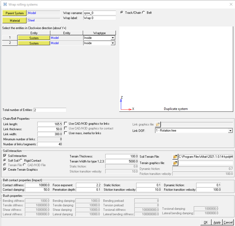
Figure 3. Wrap rolling systems dialog
The links in the belt, chain, or track are constrained to each other to prevent lateral movement. The type of constraint can be changed based on the requirement of the application. The details of the connection between the link, rolling entity, and belt, chain, or track, and the geometry type supported for each connection, is tabulated below:
| Link DOF (degree of freedom) | Connection | Lateral Constraint | Geometry Type |
|---|---|---|---|
| 1 - Rotation free | Revolute joint for all links and Inline joint between the first and last link. | Planar | Automatic, CAD |
| 1 - Rotation and bending stiffness | Revolute joint for all links and Inline joint between the first and last link. Rotational stiffness and bending preload are supported between all links. | Planar | Automatic, CAD |
| 2 - Tensile and bending stiffness | Planar joint and Inplane primitive for all links. Rotational stiffness and bending preload between all links are supported, as well as tensile stiffness and tensile preload. | Planar | Automatic, CAD |
| 6 - All direction stiffness | Tensile stiffness and Tensile preload between all links. This option supports rotational, lateral, shear, torsional, and lateral-bending stiffness, as well as bending preload between all links. | None | CAD |
The user interface automatically provides a preview of the wrapped belt, chain, or track system as soon as enough input data has been provided. If a wrap fails, error messages are displayed in the bottom of preview area. Catenary sag is included if more links than the minimum required amount are present. Conversely, there is an opening in the belt, chain, or track if the number of links are less than the minimum amount. In that case, a flexible stiffness entity is created to connect the first and last link to close the gap during simulation. This causes tension within the belt, chain, or track as soon as the simulation starts and might be preferred by design.
You can create terrain graphics and provide a Parasolid output file to visualize the terrain.
After the wrap system has been generated, additional adjustments to the properties of the system can be performed within the dataset under the rolling system.
The soft soil model can be positioned by using the Road Reference Marker.
List of Outputs Requests for Track Soil interaction
- The soil force in the global direction with respect to the refence marker for each link.
- The soil force in the link local coordinate for each link.
- Sinkage, longitudinal slip, and lateral slip for each link.
- Total soil force for each wrap.
- Total soil force for all links in all wraps.
The force output for contacts can be created for all the contacts using the Entity set option in the output request. The output for forces like tension, bending force and so on can be measured on the respective joint and or force. The mid marker in the link can be used as a reference marker for the force.
Update Link Geometry Dialog
Use this dialog to update the link geometry information of the track.
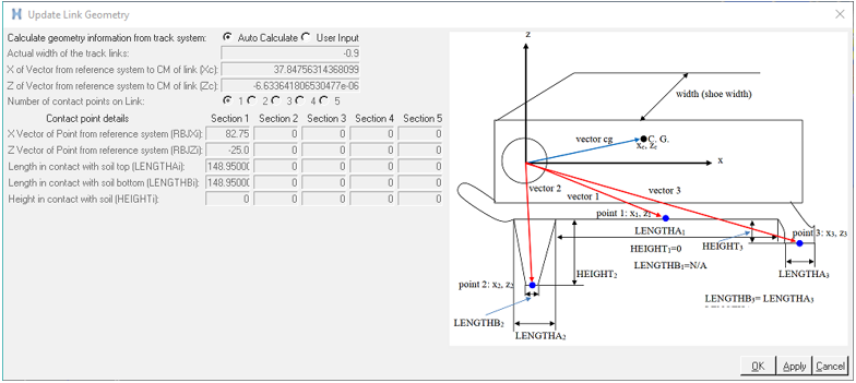
Figure 4. Update Link Geometry dialog
The fields are enabled or disabled based on the input selections. All inputs are in model units. The default values are in model units and can be modified based on application. For more information on the link geometry, see Link Geometries.
Update Soft Soil Dialog
Use this dialog to update the soil properties, which define the interaction between the soil and track link. Entities are enabled or disabled based on the input selections. All inputs are in model units. The default values are in model units and can be modified based on the application. For more information on the soft soil, see Soft-soil Data Input.
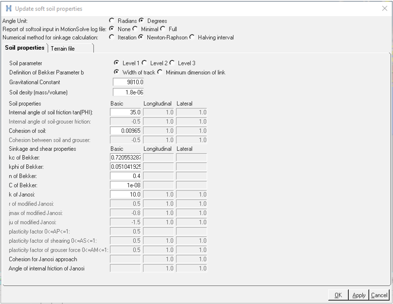
Figure 5. Update soft soil properties dialog