This type of property card is used to specify the
geometric properties of the BEAM element. Each beam
property element must have a unique identification number.
This property card defines the geometrical properties of
the beam. The material properties of the beam are defined by the
material specified by mid.
If only the dimensions at the start of the beam element
are specified, MotionSolve assumes the cross
section of the beam to be constant. However, if additionally, dimensions
at the end of the beam element are specified, then these dimensions are
varied linearly from node 1 to node 2 to represent the beam in the
animation H3D.
The attribute type defines the type of cross section for
this beam element. You may choose from the following types:
Type
Cross
section
Required
Inputs
Default
BAR
dim1a,
dim2a
dim1b = dim1a,
dim2b
= dim2a,
BOX
dim1a,
dim2a,
dim3a,
dim4a
dim1b = dim1a,
dim2b
= dim2a,
dim3b = dim3a,
dim4b =
dim4a
BOX1
dim1a, dim2a, dim3a,
dim4a
dim5a, dim6a
dim1b = dim1a,
dim2b
= dim2a,
dim3b = dim3a,
dim4b = dim4a,
dim5b = dim5a,
dim6b = dim6a
CHAN
dim1a,
dim2a,
dim3a,
dim4a
dim1b = dim1a,
dim2b
= dim2a,
dim3b = dim3a,
dim4b =
dim4a
CHAN1
dim1a,
dim2a,
dim3a,
dim4a
dim1b = dim1a,
dim2b
= dim2a,
dim3b = dim3a,
dim4b =
dim4a
CHAN2
dim1a,
dim2a,
dim3a,
dim4a
dim1b = dim1a,
dim2b
= dim2a,
dim3b = dim3a,
dim4b =
dim4a
CROSS
dim1a,
dim2a,
dim3a,
dim4a
dim1b = dim1a,
dim2b
= dim2a,
dim3b = dim3a,
dim4b =
dim4a
H
dim1a,
dim2a,
dim3a,
dim4a
dim1b = dim1a,
dim2b
= dim2a,
dim3b = dim3a,
dim4b =
dim4a
HAT
dim1a,
dim2a,
dim3a,
dim4a
dim1b = dim1a,
dim2b
= dim2a,
dim3b = dim3a,
dim4b =
dim4a
I
dim1a,
dim2a,
dim3a,
dim4a
dim5a,
dim6a
dim1b = dim1a,
dim2b
= dim2a,
dim3b = dim3a,
dim4b = dim4a,
dim5b = dim5a,
dim6b = dim6a
I1
dim1a,
dim2a,
dim3a,
dim4a
dim1b = dim1a,
dim2b
= dim2a,
dim3b = dim3a,
dim4b =
dim4a
L
dim1a,
dim2a,
dim3a,
dim4a
dim1b = dim1a,
dim2b
= dim2a,
dim3b = dim3a,
dim4b =
dim4a
T
dim1a,
dim2a,
dim3a,
dim4a
dim1b = dim1a,
dim2b
= dim2a,
dim3b = dim3a,
dim4b =
dim4a
T1
dim1a,
dim2a,
dim3a,
dim4a
dim1b = dim1a,
dim2b
= dim2a,
dim3b = dim3a,
dim4b =
dim4a
T2
dim1a,
dim2a,
dim3a,
dim4a
dim1b = dim1a,
dim2b
= dim2a,
dim3b = dim3a,
dim4b =
dim4a
Z
dim1a,
dim2a,
dim3a,
dim4a
dim1b = dim1a,
dim2b
= dim2a,
dim3b = dim3a,
dim4b =
dim4a
graph is a post-processing flag that
determines how this element will be represented in the animation H3D
file.
graph = "0" implies that
this element will not be represented in the H3D
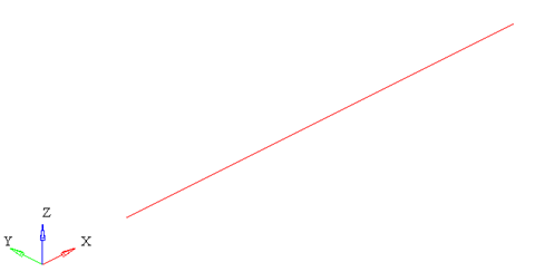
graph = "1" implies that
this element will be represented as a line drawn between
the two connecting nodes.
Figure 1. The representation of a beam with graph =
1.
Note: When using
graph="0" or
graph="1", you will
not be able to visualize the stress, strain or displacement
contours. To do this, use
graph="2" or
graph="3".
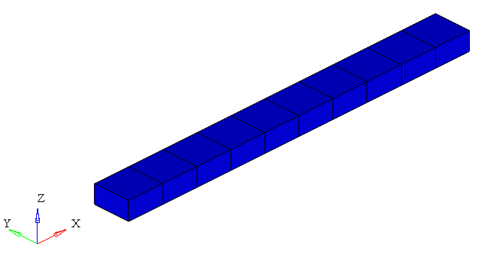
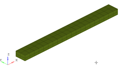
graph = "2" implies that
the beam will be represented by 3D solid elements. This
mode is useful when trying to visualize the stress/strain
and displacement contours.
Figure 2. The representation of a beam with graph =
2. The beam is represented by 3D elements
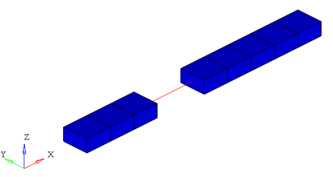
graph = "3" implies that
the beam is represented both as 3D solid elements as well
as a line connecting the two nodes of the beam. This is
useful when you need to visualize both the center line and
the 3D representation of the beam.
Figure 3. The representation of a beam with graph = 3. The 3D
elements in the middle of the beam are turned off
to show the center line of the beam
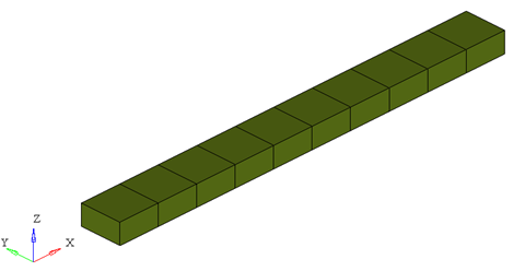
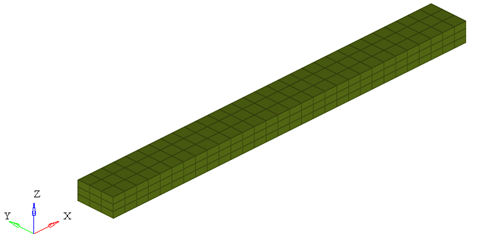
When representing the beam as a solid, the arguments
ngx, ngy and
ngz determine the number of elements
that are used to represent the beam in the animation H3D.
Figure 4. Effect of ngx, ngy and ngz on the 3D representation
of a simple beam
ngx = ngy = ngz = 1
Figure 5.
ngx = ngy = ngz = 2
Figure 6.
ngx = ngy = ngz = 3
While increasing the
ngx, ngy and
ngz results in a better representation
of the beam, it also increases the post-processing time taken by
MotionSolve to write out the
H3D. In addition, large values of ngx,
ngy and ngz will
increase the file size of the H3D considerably. Consider using
the minimum values of these attributes that satisfy your
visualization needs.