MV-7003: Simulating a Single Input Single Output (SISO) Control System Using MotionView and MotionSolve
In this tutorial, you will learn how to implement a single input single output (SISO) controller in MotionView and solve it using MotionSolve.
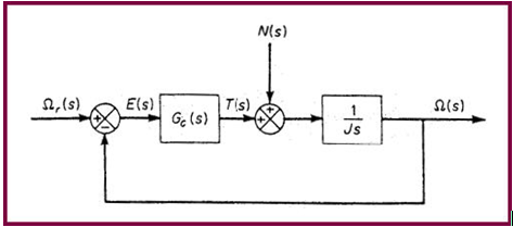
Figure 1. Block Diagram of the Control System
This tutorial shows you how to implement this PI controller.
Load the Rotor Model
Add a Solver Variable for Reference Speed
-
From the Project Browser, right-click
Model and select (or right-click
 from the toolbar.
The Add SolverVariable dialog will be displayed.
from the toolbar.
The Add SolverVariable dialog will be displayed.
Add a SISO Controller
In this section, add a SISO controller. The input to the controller is the error between the reference speed solver variable and the rotor angular speed. The output of the controller is the torque to be applied to the rotor. The parameters for the simulation are chosen, somewhat arbitrarily, as Kp=1 and K=10.
-
From the Project Browser, right-click
Model and select (or right-click
 ).
The Add Control dialog will be displayed.
).
The Add Control dialog will be displayed.
Add the Control Torque
In this section, create a control torque acting on the rotor body. The Z-component of this torque is the output of the controller.
-
From the Project Browser, right-click
Model and select (or right-click Forces
 ).
The Add Force or ForcePair dialog is displayed.
).
The Add Force or ForcePair dialog is displayed. -
Under Tz, select Expression and enter
'{MODEL.siso_0.OUTPUT}'.
Tip: You may also click
 to
access the expression builder and create this expression using the model
tree.
to
access the expression builder and create this expression using the model
tree.
Add Output Requests for Control Force
-
From the Project Browser, right-click
Model and select (or right-click
 ).
The Add Output dialog will be displayed.
).
The Add Output dialog will be displayed. -
Specify other choices as shown in the figure below:
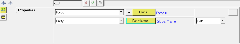
Figure 2. Setting up the Uutput Request for Control Force
Run the Simulation
-
Click Run
 to display the Run panel.
-
Click Run.
The results are displayed in the image below.
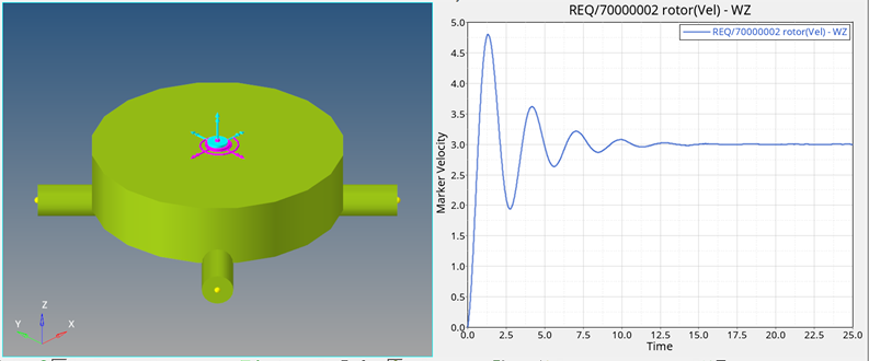
Figure 3. Simulation Results for the PI Speed Controller
Reference
K. Ogata, Modern Control Engineering, 1990, Prentice-Hall Inc., Englewood Cliffs, N.J., US