Terrain Profile Description
Input must be provided in text files. It is required to create NG files for the input of the soil profile. This parameter is defined in the input file general.dat.
The name of the input file: soil_input_i.dat, where i=1,2…,NG.
The filepath: project directory/Input_Files/Terrain/soil_input_i.dat, i=1,2…,NG
If NG=10, the path to the last file: project directory/Input_Files/Terrain/soil_input10.dat.
Parameters
- PSTYPE(i)
- Input data definition in the file soil_input(i).dat. i=1,2…,NG.
The parameters below in black are read only if PSTYPE(i)=0.
The parameters below in green are read only if PSTYPE(i)=1 or PSTYPE(i)=-1.
The parameters below in red are read only if PSTYPE(i)=2 or PSTYPE(i)=-2.
The parameters below in blue are read only if PSTYPE(i)=3 or PSTYPE(i)=-3.
- Nx, Ny
-
X_POINT(1), X_POINT(2), … , X_POINT(Nx)
Y_POINT(1), Y_POINT(2), … , Y_POINT(Ny)
Z(1,1),  Z(1,2),  …,  Z(1,Ny)
Z(2,1),  Z(2,2),  …,  Z(2,Ny)
:
Z(Nx,1),  Z(Nx,2),  …,  Z(Nx,Ny)
Z0
N_D, START_P, END_P, CENTRAL_P, R_B, Z0
NLEGS
P(1), P(2), … , P(NLEGS), P(NLEGS +1)
G_ELEV(1), G_ELEV(2), … , G_ELEV(NLEGS), G_ELEV(NLEGS +1)
Comments
- Nx(i), Ny(i)
- Number of grid lines shown on the ground in the x and y directions respectively. 2≤Nx(i)≤MNX, 2≤Ny(i)≤MNY: currently MNX=MNY=200. Nx and Ny are represented in Figure 1 by the letters n and m, respectively.
- Z(i,j)
- Ground elevation at point Xi, Yj
- Z0
- The constant ground elevation.
- N_D
- Number of segments of the circular bump. 2≤N_D≤20. Default value is 10.
- START_P, END_P, CENTRAL_P
- Coordinates along the X axis (for PSTYPE=1) or Y axis (for PSTYPE=-1). The START_P, END_P, and CENTRAL_P are the Start Point, End Point, and Central Point in Figure 2.
- R_B
- The radius of the bump. Description is provided in Figure 2.
- Z0
- Ground elevation.
- NLEGS
- The total number of the path legs in Figure 3. The parameter NLEGS is the parameter n of Figure 3.
- P(i)
- Coordinates along X axis (for PSTYPE=1) or Y axis (for PSTYPE=-1). See Figure 3.
- G_ELEV(i)
- Ground elevation at point Pi.
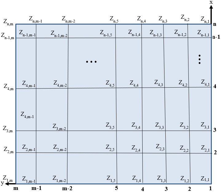
Figure 1. General description of the soil (PSTYPE=0); n points of x, m points of y, totally nXm points.
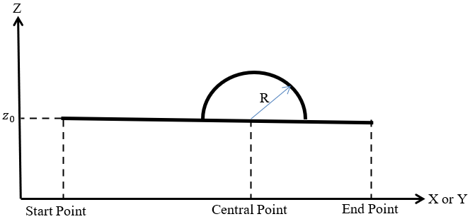
Figure 2. Circular bump (PSTYPE=1 or PSTYPE=-1)
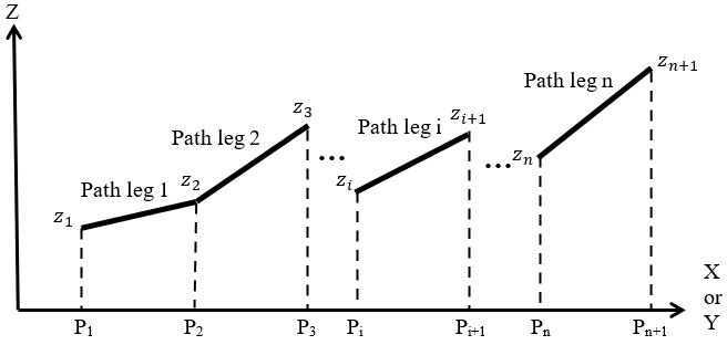
Figure 3. Path legs of various slopes (PSTYPE=2 or PSTYPE=-2)