Constraint: CVCV
Model ElementConstraint_CVCV defines higher pair constraint. The constraint consists of a 3D curve fixed on one body rolling and sliding on a 3D curve fixed on a second body. The curves are required to have a unique point of contact and a common tangent at that point of contact.
Format
<Constraint_CVCV
     id            = "integer"
   [ label         = "string" ]
     i_marker_id   = "integer"
     i_curve_id    = "integer"
   [ i_disp_x0     = "real" ]
   [ i_disp_y0     = "real" ]
   [ i_disp_z0     = "real" ]
   [ i_vel0        = "real" ]
     j_marker_id   = "integer"
     j_curve_id    = "integer"
   [ j_disp_x0     = "real" ]
   [ j_disp_y0     = "real" ]
   [ j_disp_z0     = "real" ]
   [ j_vel0        = "real" ]
   [ is_no_slip    = "real" ] >
</Constraint_CVCV>
Attributes
- id
- Element identification number (integer>0). This is a number that is unique among all Constraint_CVCV elements.
- label
- The name of the Constraint_CVCV element.
- i_marker_id
- Specifies a Reference_Marker that defines the coordinate system in which the i_curve points are defined. It also implicitly defines the body on which the curve is "etched". The curve moves with the body.
- i_curve_id
- Specifies the ID of the Reference_Paramcurve that contains the curve definition.
- i_disp_x0, i_disp_y0, i_disp_z0
-
These three parameters specify the location of the contact point on i_curve at the input configuration as measured in the i_marker_id coordinate system.
The three parameters come as a set. All three must be specified or none may be defined.
These parameters are optional.
- i_vel0
- Specifies the sliding velocity of the contact point. This velocity is measured by an observer attached to the origin of i_marker_id. The default value for i_vel0 is 0.0. When omitted, MotionSolve may change this value to satisfy system constraints.
- j_marker_id
- Specifies a Reference_Marker that defines the coordinate system in which the j_curve points are defined. It also implicitly defines the body on which the curve is "etched". The curve moves with the body.
- j_curve_id
- Specifies the ID of the Reference_Paramcurve that contains the curve definition.
- j_disp_x0, j_disp_y0, j_disp_z0
-
These three parameters specify the location of the contact point on j_curve at the input configuration as measured in the j_marker_id coordinate system.
The three parameters come as a set. Either all three or none may be specified.
These parameters are optional.
- j_vel0
-
Specifies the sliding velocity of the contact point. This velocity is measured by an observer attached to the origin of i_marker_id. This is different from what an observer on the ground sees.
The default value for j_vel0 is 0.0. When omitted, MotionSolve may change this value to satisfy system constraints when it is not specified.
- is_no_slip
-
Specifies whether the two curves are allowed to slip or slide with respect to one another. If this attribute is set to "TRUE", then this is no slip between the two curves i.e. an additional degree of freedom is removed.
The default value for is_no_slip is "FALSE"
Example
The image below shows a simple cam-follower system modeled using a Constraint_CVCV to define the cam-follower contact behavior. As the cam C rotates about its pivot, the curve-to-curve constraint forces the follower to rise up or down. Follower F is pinned to Shaft S. Thus, shaft S also rises up or down. Rotary motion of the cam is thus converted to translational motion of the shaft. The profile of the cam determines the motion of the output shaft.
The curve points defining the outline of the cam C are defined in the coordinate system of Reference_Marker I (id = 1023). The curve points are defined using the Reference_Paramcurve object with id 123.
 Figure 1. A Cam-follower System
An initial guess for the contact point on the cam-curve and the follower-curve is usually helpful. This defines the initial configuration of the higher-pair contact. Assume the contact point location on the cam-curve, as measured in the coordinate system of I, is [1.466, 5.66, 0]. Assume the contact point location on the follower-curve, as measured in the coordinate system of J, is [-0.122, 0.852, 0].
The Constraint_CVCV object may be defined as follows:
<Constraint_CVCV
     id            = "1"
     i_marker_id   = "1023"
     i_curve_id    = "123"
     i_disp_x0     = "1.466"
     i_disp_y0     = "5.66"
     i_disp_z0     = "0."
     j_marker_id   = "2046"
     j curve_id    = "246"
     j disp_x0     = "-0.122"
     j disp_y0     = "0.852"
     j disp_z0     = "0." >
</Constraint_CVCV>
Comments
- The curve-to-curve constraint is useful for modeling cams where the point of contact between two parts changes during the motion of the system. The curves always maintain contact, however, even when the physics of the model might dictate that one curve lift off the other.
- You can examine the constraint forces to determine if any lift-off should have occurred. If you would like to model lift-off, use the Force_Contact or a Force_TwoBody element.
- The curve-curve constraint removes three degrees of freedom from the system. One constraint enforces that the tangents to the two curves at the point of contact always remain parallel. This constraint prevents the bodies from spinning relative to each other about any axis normal to the common tangent at the point of contact. The other two constraints prohibit translational motion in the plane normal to the common tangent at the point of contact.
- When the body of the first curve is fixed in space, the second curve is allowed to move in three ways: It can slide along the first curve, roll on the first curve, and rotate about the common tangent at the point of contact.
- The curve-to-curve constraint does not enforce the condition that the curves remain co-planar. One or both of the curves may be 3D curves. The curves can rotate about the common tangent at the point of contact, therefore they can move out of plane even when both curves are planar curves.
- Both open and closed curves supported by Constraint_CVCV.
- Open curves have a well defined spatial extent. The curve is only defined in the domain αmin <= α <= αmax, where α is the curve parameter. While enforcing the curve-to-curve constraint, it is possible for MotionSolve to find a solution outside this range. You must define appropriate forces at the curve ends, so that the contact point stays within the domain of α.
- The curves in a Constraint_CVCV may be
convex or non-convex. A convex curve is a curve that intersects a straight line at just
two points. See the images below for examples of convex and non convex shapes. The grayish closed curve on the left in the Convex and Non-convex Curves image is an example of a convex shape. Notice that any straight line can intersect the curve at only two points. In contrast, the open curve on the right in this image is non-convex. One can draw a straight line that intersects it at more than two points.
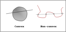 Figure 2. Convex and Non-convex Curves
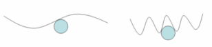 Figure 3. Single and Multiple Contacts
With non-convex curves, multiple contacts become possible, as shown in right image above. However, this does not mean that multiple contacts will necessarily occur. The image on the left in the Single and Multiple Contacts image has only one contact point even though one of the curves is clearly non-convex. Hence, when using non-convex curves, care must be taken to ensure that there is only one point of contact at all times in the simulation.
- Be suspicious of the correctness of your model, if ever one of the constraints belonging to a Constraint_CVCV is declared to be redundant. This leads to unexpected behavior and is a sure indication that the model has not been correctly built.
- MotionSolve does an initial search to exactly locate the contact point. While the attributes i_disp_x0, i_disp_y0, i_disp_z0, j_disp_x0, j_disp_y0, j_disp_z0 are not required, it is a good idea to specify them if you know what they are.