Constraint: PTdCV
Model ElementThe Constraint_PTdCV element constrains a fixed point on a body to slide along a curve that passes through the origins of a specified set of markers.
Description
These markers may belong to different bodies. As the markers move in space, the curve is calculated at every time step using CUBIC spline interpolation through the marker origins. Hence, the curve deforms as the markers move about.
This constraint is useful for simulating connection between a point on a body and a slender, flexible element such as a cable. For example, a ski chair-lift.
Format
<Constraint_PTdCV
     id                  = "integer"
   [ label               = "string" ]
     i_marker_id         = "integer"
     ref_dcurve_id       = "integer"
 />
Attributes
- id
- Element identification number, (integer>0). This number is unique among all Constraint_PTdCV elements.
- label
- The name of the Constraint_PTdCV element.
- i_marker_id
- Specifies a Reference_Marker whose origin defines the point that is constrained to move along the deformable curve.
- ref_dcurve_id
- Specifies the deformable curve used to define the Constraint_PTdCV element.
Example
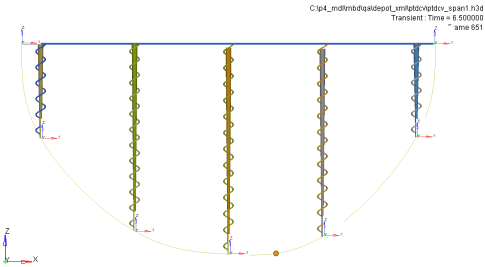 Figure 1. Application of the Constraint_PTdCV Element
The figure above shows five slender, bar-shaped rigid bodies constrained to a ground body, represented by the blue horizontal bar graphic, by translational joints with axes along the Z direction. The bodies are connected to ground by linear spring-dampers.
A deformable curve is defined to pass through seven markers shown in the figure. Five of these markers are located at the lower tips of the rigid bodies. Two of these markers are located at either end of the ground body. The deformable curve is defined using the Reference_DeformCurve element as follows:
 <Reference_DeformCurve
      id                  = "1"
      end_type_left       = "NATURAL"
      end_type_right      = "NATURAL"
      num_marker_id       = "7">
  30101120 30102061 30103071 30104081 30105091 30106101 30101130
 </Reference_DeformCurve>

 <Post_Graphic

     id                  = "500000"
      type                = "DeformCurve"
      curve_id            = "1"
      nseg                = "100"
  />
A small spherical body, shown with a yellow sphere, is constrained to slide along the deformable curve as follows:
  <Constraint_PTdCV
       id                  = "1"
       i_marker_id         = "30107060"
       ref_dcurve_id       = "1"
   />
Transient simulation of this system shows the changing shape of the deformable curve, as the sphere slides back and forth under gravity.
Comments
- The Reference_DeformCurve element does not possess any inherent inertia, stiffness, or damping properties. Additional modeling elements are necessary to capture these effects. See Example.
- The markers used to define the Reference_DeformCurve may belong to different bodies which may be of type Body_Point, Body_Rigid, or Body_Flexible.
- The Constraint_PTdCV element can be thought of as a generalization of the Constraint_PTCV element. In fact, when all the markers belong to a single rigid body, Constraint_PTdCV reduces to Constraint_PTCV.
- To correctly model a Constraint_PTdCV
element, you must ensure that the point which is referenced by the
i_marker_id will always fall in range of the deformable curve
throughout the simulation. MotionSolve calculates a u
value for the point's current position with respect to the deformable surface. This
u value must always stay within range of the defined u_span, for
example.
-u_span/2 ≤ u ≤ +u_span/2
If the current u value goes out of this range, MotionSolve will hold the u value at the boundary until the point falls back in range of the deformable curve. However, this may lead to incorrect results. You are encouraged to check the results for correctness in such a situation. For more information, please refer to the Reference_DeformCurve model element.