Force: PTdSF
Model ElementThe Force_PTdSF element defines a contact force between a deformable surface and point.
Description
The deformable surface is defined using the Reference_DeformSurface element. A sphere of an arbitrary radius is specified to be centered at the point. When the distance between the point and the surface becomes less than the sphere radius, a repulsive contact force is applied. Two types of contact force models are supported: Linear and Poisson.
Format
<Force_PTdSF
      id                    = "integer"
    [ label                 = "string" ]
      i_marker_id           = "integer"
    [ radius                = "real"   ]
      ref_dsurface_id       = "integer"
   {
      force_model           = "LINEAR"
      [ stiffness           = "real" ]
      [ damping             = "real"  ]
    |
      force_model           = "POISSON"
      [ penalty             = "real" ]
      [ restitution_coef    = "real" ]
    |
      force_model           = "USERSUB"
{
      usrsub_param_string   = "USER( [[par_1][, ...][, par_n]] )"
    [ usrsub_dll_name       = "valid_path_name"
    [ usrsub_fnc_name       = "custom_fnc_name" ]
|
      script_name           = valid_path_name
      interpreter           = "PYTHON" | "MATLAB"
      usrsub_param_string   = "USER( [[par_1][, ...][, par_n
    [ usrsub_fnc_name       = "custom_fnc_name" ]
}
   }
    [ flip_normal           = { "TRUE" | "FALSE" } ]
/>
Attributes
- id
- Element identification number (integer>0). This number is unique among all Force_PTdSF elements.
- label
- The name of the Force_PTdSF elements.
- i_marker_id
- Specifies a Reference_Marker used to define a sphere geometry. The sphere is centered at the origin of the Reference_Marker and is attached to the parent body of the Reference_Marker. The radius of this sphere is specified by the radius attribute. This sphere geometry is used for detecting contact with the deformable surface.
- radius
- Radius of the sphere geometry centered at the origin of the I marker.
- ref_dsurface_id
- Specifies the deformable surface used to define the Force_PTdSF element.
- force_model
- Select from LINEAR, POISSON or USERSUB.
- stiffness
- Stiffness coefficient for the contact force model. Only used when the force_model is set to LINEAR. The stiffness must be positive.
- damping
- Damping coefficient for the contact force model. Only used when the force_model is set to LINEAR. The damping must be positive.
- penalty
- Specifies the stiffness coefficient that is to be used for calculating the spring force. A large value for penalty permits only a small penetration between the two contacting geometries; a small value permits a larger penetration. Hertzian contact theory may be used to estimate the local stiffness. See The Roark's Formulas for Stress and Strain for more information on calculating Hertzian contact stiffness parameters. Only used when the force_model is set to POISSON. The penalty must be positive.
- restitution_coef
- Defines the coefficient of restitution (COR) between the contacting bodies. A value of zero specifies perfectly plastic contact meaning that the two bodies coalesce after contact. A value of one specifies perfectly elastic contact. No energy is lost in the collision and the relative velocity of separation equals the relative velocity of approach. Only used when the force_model is set to POISSON. The restitution_coef must lie between 0.0 and 1.0.
- usrsub_param_string
- The list of parameters that are passed from the data file to the user defined subroutine, PTDSFSUB. This attribute is common to all types of user subroutines and scripts.
- usrsub_dll_name
- Specifies the path and name of the DLL or shared library containing the user subroutine. MotionSolve uses this information to load the user subroutine in the DLL at run time.
- usrsub_fnc_name
- Specifies the name of the function to be called by MotionSolve. The default function name is PTDSFSUB.
- script_name
- Specifies the path and name of the user written script that contains the routine specified by usrsub_fnc_name. Only used when the interpreter is set to PYTHON or MATLAB.
- interpreter
- Specifies the interpreted language that the user script is written in. Valid choices are MATLAB or PYTHON.
- flip_normal
- A Boolean flag (TRUE/TRUE).
- TRUE
- The element normals are generated using the right hand rule. Specifically, if one curls the fingers of the right hand in the order N1, N2, and N3 of a triangular element, then the thumb provides the direction of the normal vector.
- TRUE
- The normal vector points in the direction opposite to the right hand thumb.
Example 1
<Reference_DeformSurface
      id                  = "1"
      end_type            = "NATURAL"
      num_marker_row      = "7"
      num_marker_col      = "7">
 30101490 30101500 30101510 30101520 30101530 30101540 30101540
 30101420 30109781 30113791 30117801 30121811 30125821 30101480
 30101350 30108711 30112721 30116731 30120741 30124751 30101410
 30101120 30102061 30103071 30104081 30105091 30106101 30101130
 30101140 30110571 30114581 30118591 30122601 30126611 30101200
 30101210 30111641 30115651 30119661 30123671 30127681 30101270
 30101280 30101290 30101300 30101310 30101320 30101330 30101340
  </Reference_DeformSurface>

<Force_PTdSF
     id                  = "1"
     i_marker_id         = "30107850"
     radius              = "10.0"
     ref_dsurface_id     = "1"
     force_model         = "LINEAR"
     stiffness           = "1000.0"
     damping             = "0.1"
 />


<Post_Graphic
     id                  = "500000"
     type                = "DeformSurface"
     surface_id          = "1"
     nseg_u              = "30"
     nseg_v              = "30"
/>Comments
- Force_PTdSF element calculates a repulsive
force based on the distance between the point and the deformable surface and the
Force_PTdSF element properties:
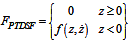
where

Force_PTdSF may thus be used to simulate flex to rigid body contact by attaching the deformable surface to the nodes of a flexible body.
- Friction is supported through user subroutines. The Force_PTdSF element defines a contact force between a rigid body and a deformable surface. This modeling element has been enhanced to support user-defined models for contact normal force and frictional force. A user subroutine, PTDSFSUB, is required to provide the user-defined contact models. PTDSFSUB may be written in Fortran, C or C++ languages, or alternatively in Python or MATLAB scripts.
- The output signals from a Force_PTdSF that
are written to the MotionSolve Results File (MRF) and Altair
Binary File (ABF) have been extended to include the following time based quantities:
- The X-Y-Z locations of the contact point.
- The X-Y-Z components of the surface normal at the contact point.
- The penetration depth.
- The contact normal force (which acts along the surface normal).
- The X-Y-Z components of the friction force vector.
- The U and V parameter values for the surface at the contact point.
- The tracking error, a measure of how accurately the contact point has been determined.
MRF/ABF Component Description CONTACT P(X) CONTACT P(Y)
CONTACT P(Z)
The X, Y, Z locations of the contact point. NORMAL VEC(X) NORMAL VEC(Y)
NORMAL VEC(Z)
The X, Y, Z components of the surface normal at the contact point. PARAM U PARAM V
The U and V parameter values for the surface at the contact point. PENETRATION (Z) Penetration depth along the surface normal at the contact point. TRACKING ERROR(L) The tracking error – a measure of how accurately the contact point has been detected. CONTACT FORCE (FN) The contact normal force that acts along the surface normal at the point of contact. FRICTION FORCE (Fx) FRICTION FORCE (Fy)
FRICTION FORCE (Fz)
The X, Y, Z components of the friction force.
Note:- The contact normal vector points outward from the deformable surface.
- If PENETRATION (Z)≤ 0, there is no contact. The magnitude can be interpreted as the distance of the I marker to the closest point on the deformable surface.
- Contact only occurs when PENETRATION (Z) > 0.
- U and V are the parameters of the bi-cubic spline with variable knot positions that are used to represent the deformable surface.
- The tracking error can be controlled by changing the integration tolerance (integr_tol) and the constraint tolerance (dae_constr_tol) specified in the Param_Transient entity. Typically, during contact, the tracking error L should stay below a fraction of the penetration Z.
- The components of all vectors are defined in the global coordinate system. These quantities can now be plotted in HyperGraph.
- A family of Force_PTdSF elements may be used to model contact between two deformable surfaces. However, there must be only one contact point between the two surfaces. One common application is to analyze moan and squeal phenomena in disk brakes.
- To correctly model a Force_PTdSF element,
you must ensure that the point which is referenced by the i_marker_id
stays within the area defined by the normal projection of the deformable surface throughout
the simulation. MotionSolve calculates a (u, v) value for the
point's current position with respect to the deformable surface. This (u, v) value must
always stay within range of the defined u_span and v_span, for example.
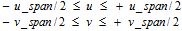
If the current u or v value goes out of this range, MotionSolve will not calculate a force for that element. However, this may lead to incorrect results. You are encouraged to check the results for correctness in such a situation. For more information, please refer to the Reference_DeformSurface model element.
- Unlike the Constraint_PTdSF element, the Force_PTdSF element permits lift-off. As long as the point remains within the "u" and "v" range, the normal distance between the point and the deformable surface is allowed to be greater than the value specified in the attribute radius.