OS-E: 0710 Application of a GENEL Element
GENEL elements can be used to define kinematic responses between two nodes.
The GENEL element is defined with Grid ID's and a 12 by 12 matrix in the Basic system. Associated degrees of freedom are the three translations and three rotations at both nodes.
Model Files
Refer to Access the Model Files to download the required model file(s).
The model file used in this example includes:
Beam_vs_GENEL.fem
Model Description
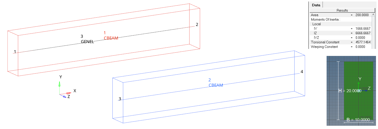
Figure 1. Model and Beam Sections
- Property
- Young’s Modulus
- 1MPa
- Poisson's Ratio
- 0.3
- Property
- Young’s Modulus
- 210 GPa
- Poisson's Ratio
- 0.3
The only purpose of Element 1 is to provide visualization in HyperView. The GENEL element is also applied between grids 1 and 2. The GENEL element is defined using the Euler-Bernoulli beam theory, which does not consider shear deformation like the Timoshenko-based beam used in OptiStruct. The beam is clamped at the left end and four subcases are defined for each, including a single force or moment component at the right end. The beam length is 100mm and shear deformation is rather insignificant. Element 2 is slightly more flexible in bending load cases than GENEL.
- E
- Young's modulus
- A
- Cross-sectional area
- L
- Length
- I
- Second moment of inertia
- G
- Shear modulus
- J
- Polar moment of inertia
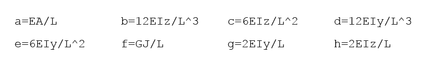
- a, b, …, h
- Populated in the 12 by 12 stiffness matrix (see Figure 2, left).
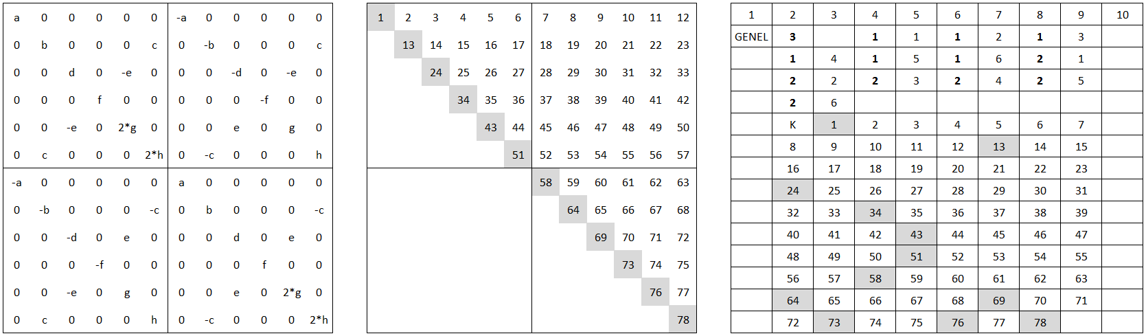
Figure 2. Beam Element Stiffness Matrix, 78 Coefficients for Symmetric Matrix, GENEL Element Bulk Data Card for Stiffness Matrix
Results

Figure 3. GENEL and Beam Element Displacement in Bending