CIFHEX
Bulk Data Entry Defines the connections of the cohesive element.
Format
| (1) | (2) | (3) | (4) | (5) | (6) | (7) | (8) | (9) | (10) |
|---|---|---|---|---|---|---|---|---|---|
| CIFHEX | EID | PID | G1 | G2 | G3 | G4 | G5 | G6 | |
| G7 | G8 | G9 | G10 | G11 | G12 | G13 | G14 | ||
| G15 | G16 |
Example
| (1) | (2) | (3) | (4) | (5) | (6) | (7) | (8) | (9) | (10) |
|---|---|---|---|---|---|---|---|---|---|
| CIFHEX | 101 | 4 | 3 | 4 | 5 | 6 | 7 | 8 | |
| 9 | 10 |
| (1) | (2) | (3) | (4) | (5) | (6) | (7) | (8) | (9) | (10) |
|---|---|---|---|---|---|---|---|---|---|
| CIFHEX | 101 | 4 | 3 | 4 | 5 | 6 | 7 | 8 | |
| 9 | 10 | 11 | 12 | 13 | 14 | 15 | 16 | ||
| 17 | 18 |
Definitions
| Field | Contents | SI Unit Example |
|---|---|---|
| EID | Unique element
identification number. No default (Integer > 0) |
|
| PID | A PCOHE
property entry identification number. Default = EID (Integer > 0) |
|
| G# | Grid point identification
numbers of connection points. No default (Integer > 0) |
Comments
- Corner grid points
G1 through G4 should be input in
consecutive order at the bottom face of the cohesive element. Corner grid points
G5 through G8 should be defined on the
top face with G5 opposite G1,
G6 opposite G2, and so on.
If existing, the edge grid points G9 through G12 should be provided in consecutive order at the bottom face of the cohesive element. Edge grid points G13 through G16 should be on the top face with G13 opposite G9, G14 opposite G10, and so on.
The top and the bottom faces can coincide initially.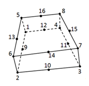
Figure 1. - The element coordinate system for the
CIFHEX element is.
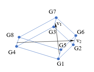
Figure 2.Two intermediate vectors, v1 and v2, are defined. v1 starts from the middle point between G1 and G5 and points to the middle point between G3 and G7. v2 starts from the middle point between G4 and G8 and points to the middle point between G2 and G6. The z-axis of the element coordinate system is obtained by the cross product of v2 and v1. The x-axis is the bisection vector of v1 and v2. Finally, the y-axis is obtained by the cross product of the z- and x- axes.
- The cohesive material coordinate system is the same as the element coordinate system by default and can be defined as a prescribed system through the PCOHE entry.