OS-T: 1370 Complex Eigenvalue Analysis of a Reduced Brake System

In this tutorial, a modal complex eigenvalue analysis is performed on a simplified brake system to determine whether the friction effects can cause any squeal noise (unstable modes).

The simplified brake system consists of a brake pad with frictional surface and back plate, and a contact plate. They were all modeled with solid elements. Spring elements (CELAS1) were created between the brake pad and the contact plate to measure the normal contact forces, as shown in Figure 1. The friction forces on the pad and the contact plate are proportional to the normal contact forces. The stiffness matrix terms representing the relationship between friction forces and normal displacements on the contact grids were saved in a DMIG bulk data file DMIG.pch. Assume the brake pad is in full contact with the plate at all time. The back plate of the brake pad and the contact plate were constrained to the ground.

rd2110_model_review
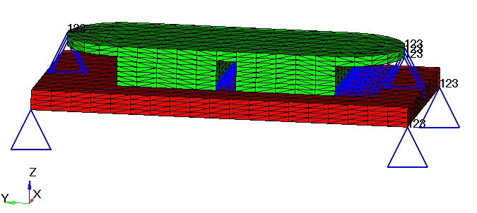
Figure 1. Model Review

Launch HyperMesh and Set the OptiStruct User Profile

  1. Launch HyperMesh.
    The User Profile dialog opens.
  2. Select OptiStruct and click OK.
    This loads the user profile. It includes the appropriate template, macro menu, and import reader, paring down the functionality of HyperMesh to what is relevant for generating models for OptiStruct.

Import the Model

  1. Click File > Import > Solver Deck.
    An Import tab is added to your tab menu.
  2. For the File type, select OptiStruct.
  3. Select the Files icon files_panel.
    A Select OptiStruct file browser opens.
  4. Select the brake.fem file you saved to your working directory. Refer to Access the Model Files.
  5. Click Open.
  6. Click Import, then click Close to close the Import tab.

Set Up the Model

Create EIGRL and EIGC Cards

In this step, a modal method is used to solve the complex eigenvalue problem, which is more computationally efficient compared to extracting the complex modes directly. With this approach, first, the real modes are calculated via a normal modes analysis. Then, a complex eigenvalue problem is formed on the projected subspace spanned by the real modes and thus much smaller than the real space. In this case, both EIGRL and EIGC cards need to be defined.
  1. In the Model Browser, right-click and select Create > Load Collector.
  2. For Name, enter eigrl.
  3. Click Color and select a color from the color palette.
  4. For Card Image, select EIGRL from the drop-down menu.
  5. For ND, enter 20.
    20 real modes are required to produce the reduced space for complex eigenvalue analysis.
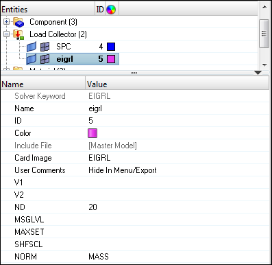
    os_1370_01
    Figure 2.
  6. Create another load collector named eigc.
  7. For Card Image, select EIGC.
  8. For NORM, select MAX.
    MAX option is used to normalize the eigenvectors.
  9. For ND0, enter 12.
    The desired number of roots to be extracted is 12.

Retrieve Friction Data and Define Analysis Parameters

  1. Go to the Analysis page, then click control cards.
  2. Click INCLUDE_BULK.
  3. Input the name of the include file, DMIG.pch.
  4. Click return to go back to control cards.
  5. Click K2PP.
  6. In K2PP panel, set number_of_k2pps= 1.
  7. In the field of K2PP=, enter KF.
    KF is the name of the DMIG Data Entry.
  8. Click return and back to control cards.

Retrieve the friction coefficients from the DMIG.pch file.

  1. Click PARAM.
  2. Check the small box in front of parameter G.
  3. Click [G_V1] and input 0.2 as the structural damping coefficient.
  4. Check the small box in front of parameter FRIC.
  5. Click [VALUE] and input 0.05.
    Friction factor 0.05 is used to scale the friction coefficient from DMIG Data Entry.
  6. Click return twice and go back to the Analysis page.

Define a Load Step for Modal Complex Eigenvalue Analysis

  1. In the Model Browser, right-click and select Create > Load Step.
  2. For Name, enter complex_eigen.
  3. Click Analysis type and select Complex eigen (modal) from the drop-down menu.
  4. For SPC, click Unspecified > Loadcol.
  5. In the Select Loadcol dialog, select SPC from the list of load collectors and click OK.
  6. For CMETHOD, click Unspecified > Loadcol.
  7. In the Select Loadcol dialog, select eigc from the list of load collectors and click OK.
  8. For METHOD(STRUCT), click Unspecified > Loadcol.
  9. In the Select Loadcol dialog, select eigrl from the list of load collectors and click OK.

Submit the Job

  1. From the Analysis page, click the OptiStruct panel.

    OS_1000_13_17
    Figure 3. Accessing the OptiStruct Panel
  2. Click save as.
  3. In the Save As dialog, specify location to write the OptiStruct model file and enter brake_complex for filename.
    For OptiStruct input decks, .fem is the recommended extension.
  4. Click Save.
    The input file field displays the filename and location specified in the Save As dialog.
  5. Set the export options toggle to all.
  6. Set the run options toggle to analysis.
  7. Set the memory options toggle to memory default.
  8. Click OptiStruct to launch the OptiStruct job.
If the job is successful, new results files should be in the directory where the brake_complex.fem was written. The brake_complex.out file is a good place to look for error messages that could help debug the input deck if any errors are present.

View the Results

Complex eigenvalue analysis computes the complex modes of the structure. The eigenvalues of the complex modes can be found in brake_complex.out file. The complex eigenvectors can be reviewed in HyperView.
  1. Load the brake_complex.out file in a text editor.
    The complex modes contain the imaginary part, which represents the cyclic frequency, and the real part which represents the damping of the mode. If the real part is negative, then the mode is said to be stable. (For complex eigenvalue analysis, such unstable modes are also indicated by an asterisk next to the mode number). If the real part is positive, then the mode is unstable. The eigenvalues of the complex modes are shown below:
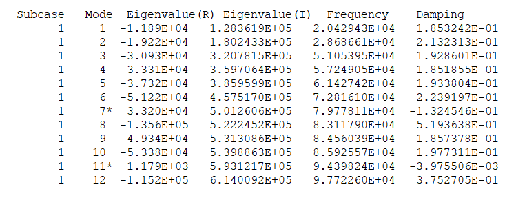
    rd2110_eigenvalues
    Figure 4.

    It can be observed that the 7th and 11th modes are unstable, while all the other modes are stable.

    The friction coefficient parameter can be reduced by setting the PARAM,FRIC factor from a value of 0.05 to 0.01, and all roots become stable. It illustrates that there is a stability threshold between the friction factor 0.05 and 0.01. It can be determined by resetting the scale factor of PARAM, FRIC and rerunning the model till the damping value of this mode approaches zero.

  2. Load the brake_complex.h3d file into HyperView to review complex eigenvectors.