The objective is to compute the magnetic force in Flux
which will act as an input in OptiStruct for structural
analysis or optimization.
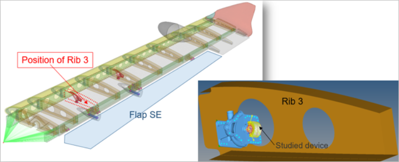
The device used here is a fuel pump permanent magnet motor implemented in an airplane
wing. The motor is brushless AC permanent magnet motor in which the electromagnetic
analysis is done using Flux. Figure 2.
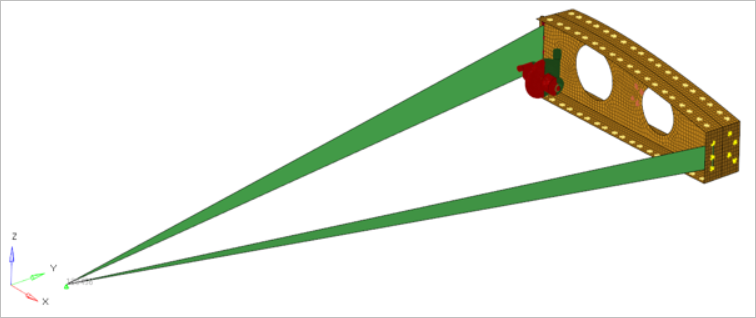
To reduce the computation time, 3 different superelements have been generated. The
initial model contains the fuel pump with the motor and the rib, and the links to
the superelements. The motor model has been designed in Flux 2D. The fuel pump is attached to the web of wing body
Rib03 using 12 fasteners. The objective is to evaluate the electromagnetic
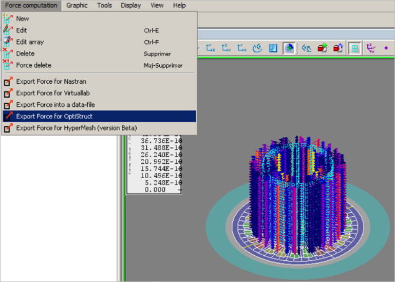
performances and to compute the forces. The mechanical mesh is imported from
HyperMesh to Flux and
after computing, the forces are exported for OptiStruct.
This electromagnetic performance can be used to define constraints and the forces
can be used as loads in the OptiStruct analysis.
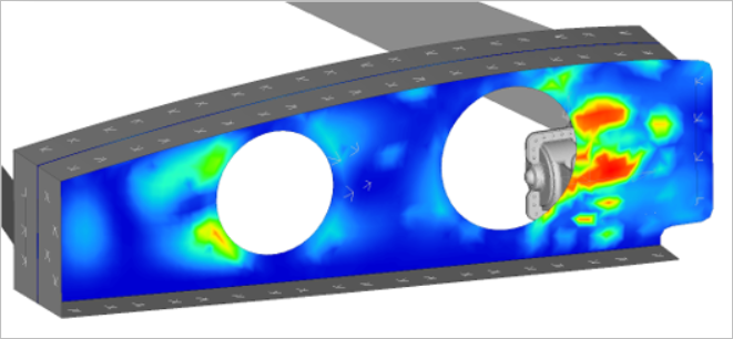
Frequency response analysis is performed in OptiStruct
using the forces extracted from Flux and the Equivalent
Radiated Power (ERP) output is requested on the Rib03 web. Figure 3. Forces extracted from and the Equivalent Radiated Power (ERP)
output
Note:
For additional details regarding the input from Flux , refer to the Flux documentation.
The forces from Flux are provided in the
cartesian coordinate system. As the forces are calculated using Flux2D,
there is no axial (Z) component of forces. Thus, in the nodes where
forces are applied, the calculations are performed in a cartesian
coordinate system and not in a cylindrical coordinate system.
Further,
as the stator in the OptiStruct model is
not oriented along the global Z axis, a local rectangular system is
used to apply the loads in the correct directions.
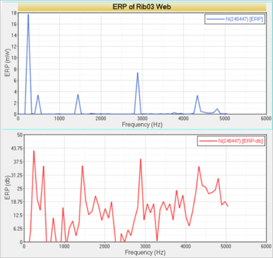
Results
Figure 4. Equivalent Response Power (ERP) on the Wing Body Figure 5. Variation of ERP (in mW and db) with Frequency