OS-E: 3000 Cross-section Optimization of a Spot Welded Tube
A tube made of two sheet metal pieces is intended to carry a load in both bending and torsion. The cross-section of the tube may be of any shape, but due to manufacturing requirements, it must remain constant through the entire length.
Model Files
Refer to Access the Model Files to download the required model file(s).
The model file used in this example includes:
tube.fem
Model Description
Conventional shape optimization can be used to optimize the cross-section, but setting up the variables is time consuming. With topography optimization and pattern grouping, cross-section shape optimization can be performed in a fraction of the set up time. All optimization set up is done using the Optimization panel and its subpanels in HyperMesh.
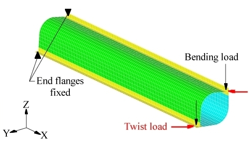
Figure 1. Loads and Constraints for the Spot Welded Tube
| (1) | (2) | (3) | (4) | (5) | (6) | (7) | (8) | (9) | (10) |
|---|---|---|---|---|---|---|---|---|---|
| DTPG | 1 | PSHELL | 1 | ||||||
| + | 2.5 | 85.0 | NO | 5.0 | NORM | NONE | |||
| + | PATRN | 1 | 0.0 | 0.0 | 0.0 | 1.0 | 0.0 | 0.0 |
The draw height of 5.0, combined with the upper and lower bounds of 2.0 and -2.0, allow a bead height of 10.0 model units in both directions (inward and outward) and a bead growth direction normal to the surface of the tube. A linear type pattern grouping is applied for this problem. This means that the beads formed during the topology optimization will be constant along a line parallel to the direction defined -- the central axis (X-axis) of the tube, in this case. By setting this pattern grouping option, the cross-section of the tube will be allowed to change, but will remain constant through the length of the tube.
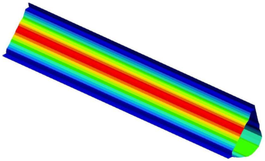
Figure 2. Optimized Cross-Section for the Tube
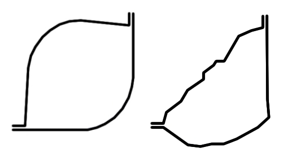
Figure 3. Cross-Sections of the Tube Before and After Optimization
Results
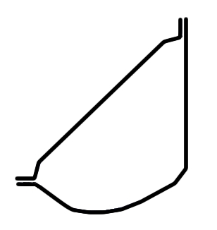
Figure 4. Smoothed Cross-Section of the Tube
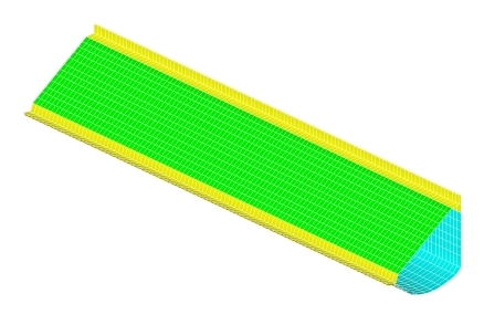
Figure 5. Finite Element Model of the Smoothed Optimized Tube