CTPSTN
Bulk Data Entry Defines a plane strain triangular element in x-z or x-y plane.
Format
| (1) | (2) | (3) | (4) | (5) | (6) | (7) | (8) | (9) | (10) |
|---|---|---|---|---|---|---|---|---|---|
| CTPSTN | EID | PID | G1 | G2 | G3 | G4 | G5 | G6 | |
| THETA |
Example
| (1) | (2) | (3) | (4) | (5) | (6) | (7) | (8) | (9) | (10) |
|---|---|---|---|---|---|---|---|---|---|
| CTPSTN | 111 | 2 | 31 | 74 | 75 | 32 | 51 | 52 | |
| 15.0 |
Definition
| Field | Contents | SI Unit Example |
|---|---|---|
| EID | Unique element
identification number. No default (Integer > 0) |
|
| PID | A
PPLANE entry identification
number. Default = EID (Integer > 0) |
|
| G1, G2, G3 | Identification numbers
of connected corner grid points. These fields are mandatory. No default (Integers > 0, all unique) |
|
| G4, G5, G6 | Identification numbers
of connected edge grid points. Default = blank (Integers > 0 or blank) |
|
| THETA | Material orientation angle in
degrees. Default = 0.0 (Real) |
Comments
- Element identification numbers must be unique with respect to all other element identification numbers.
- The Grid ordering of
G1 through G6 are defined as:
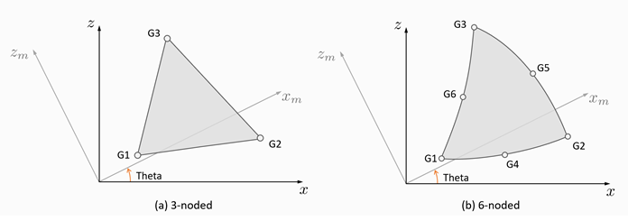
Figure 1. CTPSTN Definition - The continuation line is optional.
- If the PPLANE entry referenced in field 3 references a MAT3 entry, material properties and stresses are always given in the xm-zm coordinate system shown in Figure 1.
- Plane strain analysis defined in x-y plane is supported, i.e. the axis labels of “z” above can be replaced by “y”.
- A concentrated load (for example,
a load specified by a FORCE entry) at a grid
Gi of this element is defined to distribute along the
thickness, T, of the element. For example, in order to apply a load of 200
N/m to a node Gi with the element thickness being 5.0m,
the amount to be specified on the load entry should be:
(1) The default thickness of 1.0 is used, if T is not specified on the PPLANE entry.
- Plane strain elements are supported in linear analysis, small and large displacement nonlinear static analyses. They are currently not supported for large displacement inertia relief analysis.