Keyword used for ID ranges to indicate that all IDs between
the preceding ID and the following ID are to be included in the
set.
This is applicable only for Format 2.
Comments
CYJOIN and
CYSYM Bulk Data Entries are required in
cyclic symmetry analysis.
Supported analysis types include
linear static (STATIC) and normal mode analysis (MODES). For normal mode
analysis, currently only Lanczos (EIGRL) and Lapack-based
dense (EIGRD) solvers are supported.
Two homologous
CYJOIN entries should be defined respectively for
both SIDE 1 and SIDE 2 of a segment.
Each grid on a CYJOIN entry should be paired with a
matching grid on the other entry. Mismatched grid pairs would result in loss
of accuracy, and in such cases a warning that lists mismatched grids will be
printed to the .out file.
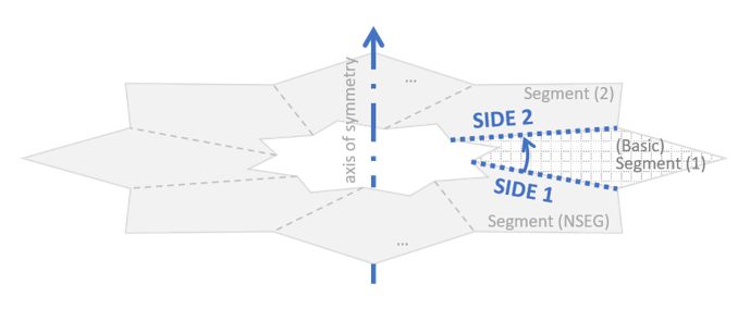
The two cyclic boundaries of the
modeled segment which are to be connected to adjacent segments are defined
as SIDE 1 and SIDE 2. The positive
direction of the axis of symmetry is defined such that
SIDE 1 and SIDE 2 are numbered
sequentially in the counter clockwise order about the axis. Figure 1. Axis of symmetry and cyclic boundaries of the basic
segment
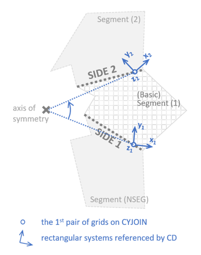
The axis of cyclic symmetry is
determined by the geometry and CD fields of the first
pair of grids appearing on CYJOIN entries. Hence, the
displacement coordinate systems (the CD field on GRID Bulk Data Entry) of the first grid pair should
be consistent between the CYJOIN entries. This
requirement could be easily satisfied by using a spherical or cylindrical
coordinate system placed on the axis of symmetry. An example of consistent
rectangular coordinate systems for CYJOIN is illustrated
in Figure 2. Figure 2. Illustration of consistency of the coordinate systems
for CYJOIN
If PARAM, AXCYSYM, YES is present,
the axis of symmetry will be defined by grids on the CYAX
entry, and the restrictions in Comment 5 regarding the CD
fields of grids on CYJOIN no longer apply. Refer to
PARAM, AXCYSYM for more details.
At the segment interfaces, all
components of displacement at GIDi are constrained to
adjacent segments during the analysis, except those constrained by SPC, or
assigned dependent by MPC, RBE2 and
RBE3.