OS-T: 1960 Define Point to Deformable Curve Joint
In this tutorial, a multibody dynamics analysis (simulation type: Transient Analysis) of a hook on a flexible cable are performed using OptiStruct.

Figure 1. Hook Rolling on a Cable
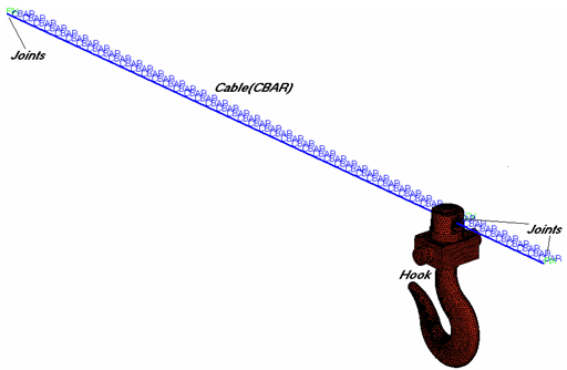
Figure 2. Model in HyperMesh
The flexible cable consists of 50 different CBAR elements (PFBODY) and the end of this flexible body is connected to ground (GROUND) using fixed joints.
The Hook (PRBODY) is an external graphic and is connected to the flexible cable by the PTDCV joint.
Launch HyperMesh and Set the OptiStruct User Profile
Open the Model
Set Up the Model
Create Rigid Bodies (PRBODY)
- From the Analysis page, click the bodies panel.
- Select the create subpanel.
- In the body= field, enter Hook.
- Click type= and select PRBODY.
- Using the props selector, select Hook.
- Double-click nodes and select by id, then enter 14399.
- Click create.
- Click return.
Create Flex Bodies (PFBODY)
-
Toggle number of modes to nmodes=, and enter
15.
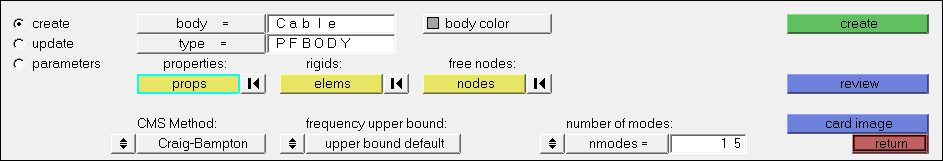
Figure 3.
Create GROUND Bodies (GROUND)
- From the Analysis page, click the bodies panel.
- Select the create subpanel.
- In the body= field, enter Ground.
- Click type= and select GROUND.
- Double-click nodes and select by id, then enter 14397, 14398.
- Click create.
Define the Deformable Curve
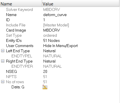
Figure 4.
Create Joints
You will create all the necessary joints including the PTDCV joint.
-
Create the PTDCV joint.
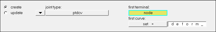
Figure 5.
Create Load Collectors
In this step you will create the gravity force that applies to the model and MBSIM Bulk Data card, which is to specify the parameter for multibody simulation.
-
Input the values as illustrated below.
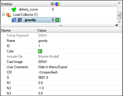
Figure 6. -
Create another load collector.
-
Input the values as illustrated below.
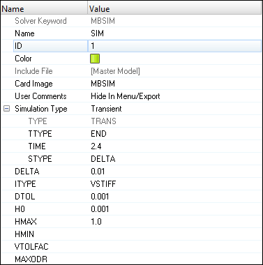
Figure 7.
-
Input the values as illustrated below.
Create Load Steps
Submit the Job
-
From the Analysis page, click the OptiStruct
panel.

Figure 8. Accessing the OptiStruct Panel
- flex_cable.html
- HTML report of the analysis, providing a summary of the problem formulation and the analysis results.
- flex_cable.out
- OptiStruct output file containing specific information on the file setup, the setup of your optimization problem, estimates for the amount of RAM and disk space required for the run, information for each of the optimization iterations, and compute time information. Review this file for warnings and errors.
- flex_cable.h3d
- HyperView binary results file.
- flex_cable.res
- HyperMesh binary results file.
- flex_cable.stat
- Summary, providing CPU information for each step during analysis process.
View the Results
In this step you will view the results in HyperView, which will be launched from within the OptiStruct panel of HyperMesh.
HyperView is a complete post-processing and visualization environment for finite element analysis (FEA), multibody system simulation, video and engineering data.
-
Click the Contour panel toolbar icon
 .
.
-
Start/stop the animation using the Animation Controls in the panel next to the
playback controls.
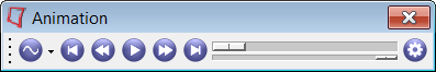
Figure 9.-
Verify Animate Mode is set to
 (Transient).
- Click the Start/Pause Animation icon to start the animation.
- With the animation running, use the bottom slider bar to adjust the speed of the animation.
- Click the Start/Pause Animation icon again to stop the animation.
-
Verify Animate Mode is set to