Free-size Optimization
Free-size optimization is defined through the DSIZE Bulk Data Entry that is supported in the HyperMesh Optimization panel.
Features available for free-size include: minimum member size control, symmetry, pattern grouping and pattern repetition, and stress constraints applied to von Mises stresses of the entire structure.
Involving both topology and free-size in the same optimization problem is not recommended, since penalization on topology components creates a bias that could lead to sub-optimal solutions.
Problem Formulation
For a shell cross-section, free-size optimization allows thickness t to vary freely between T and T0 for each element; this is in contrast to topology optimization which targets a discrete thickness of either T or T0.

Figure 1. Shell Cross-section
Example: Cantilever Plate
The cantilever plate is shown in the following figure. Base-plate thickness T0 is zero. The optimization problem is stated as:
Minimize Compliance
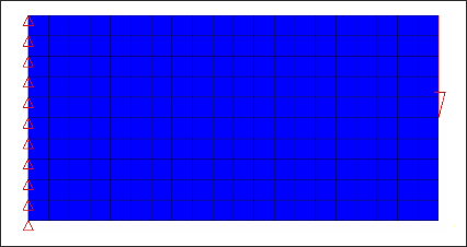
Figure 2. Cantilever Plate
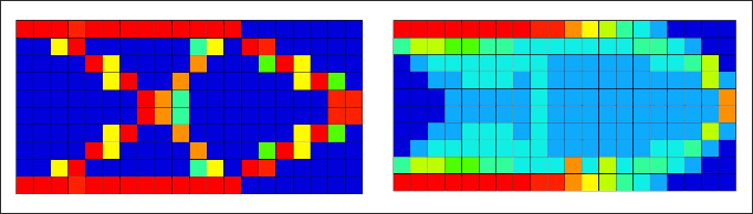
Figure 3. Topology Result (left); Free-size Result (right)
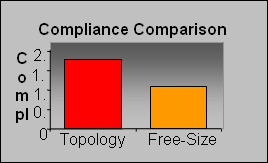
Figure 4.
It is not surprising to see that the free-size design outperforms the topology design in terms of compliance since continuous variation of thickness offers more design freedom.
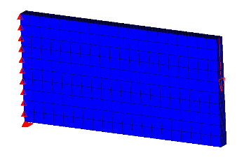
Figure 5. Cantilever Plate - 3D Model
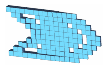
Figure 6. 3D Topology Result
The topology design of the 3D model shown above looks similar to the free-size results shown previously. This should not be surprising because when the plate is modeled in 3D, a variable thickness distribution becomes possible under the topology formulation that seeks a discrete density value of either 0 or 1 for each element. If infinitely fine 3D elements are used, a continuous variable thickness of the plate can be achieved via topology optimization. The motivation for the introduction of free-size is based on the conviction that limitations due to 2D modeling should not become a barrier for optimization formulation. In regards to the 3D modeling of shell, topology optimization is equivalent to the application of extrusion constraint(s) in the thickness direction of a 3D modeled shell.
It is important to point out that while free-size often creates variable thickness shells without extensive cavity, it does not prevent cavity if the optimizer demands it. In the example already shown, there is cavity in the free-size result in the 45 degree region, adjacent to the support, and in the upper and lower corners of the free end.
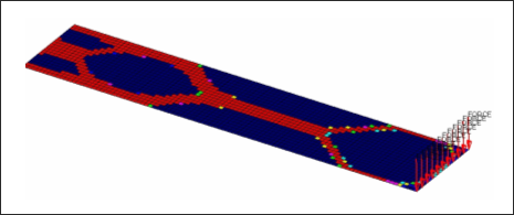
Figure 7. Free-size Result of a Plate under Bending
Stress Responses for Topology and Free-Size Optimization
Actual Stress Responses for Topology and Free-Size Optimization are available through corresponding Stress response RTYPE's on the DRESP1 Bulk Data Entry. The Stress-NORM aggregation is internally used to calculate the Stress Responses for groups of elements in the model.
von Mises Stress in a Topology or Free-Size Optimization
- The definition of stress constraints is limited to a single von Mises permissible stress. The phenomenon of singular topology is pronounced when different materials with different permissible stresses exist in a structure. Singular topology refers to the problem associated with the conditional nature of stress constraints, i.e. the stress constraint of an element disappears when the element vanishes. This creates another problem in that a huge number of reduced problems exist with solutions that cannot usually be found by a gradient-based optimizer in the full design space.
- Stress constraints for a partial domain of the structure are not allowed because they often create an ill-posed optimization problem since elimination of the partial domain would remove all stress constraints. Consequently, the stress constraint applies to the entire model when active, including both design and non-design regions, and stress constraint settings must be identical for all DSIZE and DTPL cards.
- The capability has built-in intelligence to filter out artificial stress concentrations around point loads and point boundary conditions. Stress concentrations, due to boundary geometry are also filtered to some extent as they can be improved more effectively with local shape optimization.
- Due to the large number of elements with active stress constraints, no element stress report is given in the table of retained constraints in the .out file. The iterative history of the stress state of the model can be viewed in HyperView or HyperMesh.
- Stress constraints do not apply to 1D elements.
- Stress constraints may not be used when enforced displacements are present in the model.
Compare Design Characteristics of Topology and Free-size
The differences in the characteristics of topology and free-size are summarized in the table below. It is important to note that while the free-size design concept generally achieves better performance when buckling constraints are ignored, the topology concept could outperform free-size, if buckling constraints become the driving criteria during the size and/or shape optimization stage. The reason for this is that topology optimization eliminates intermediate thicknesses, which leads to a more concentrated material distribution and a shell that is stronger against out-of-plane buckling. The performance of topology and free-size is compared in an example below. Since it is usually not possible to know what criteria are most critical for a given structure, it is recommended to follow both design concepts until detailed size and shape optimization is complete and can be evaluated. If it is not possible to derive two designs for every structural component, a benchmark of the relative performance of both concepts for every type of commonly evaluated structure should be established so that general guidelines can be used for reference.
- A variable thickness shell is typically far more expensive to manufacture and may not be a viable choice; as with most shell structures of an automobile that are manufactured using standard sheet metal, for example.
- The functionality of the structure might require extensive cavity in the design; as with an airplane fuselage floor supporting beam which may need a significant amount of cavity to allow for the pass-through of wires, pipes or other equipment.
| Shell Topology Optimization | Free-size |
|---|---|
| GOAL: 0/1 thickness Restricted freedom |
GOAL: variable
thickness "Free" under upper bound T |
| Results: Truss-like design concepts. | Variable thickness panel likely for in-plane loading, 0/1 thickness likely when bending is dominant. |
| Equivalent to extrusion constraints when shell is modeled in infinitely fine 3D elements. | Equivalent to model with infinitely fine 3D elements. |
| Not useful compared to free-size? | Always better design? |
| Manufacturing constraint - punched sheet metal of constant thickness. | Manufacture - expensive and only used in industries less sensitive to cost. |
| Concentrated full thick members are stronger against out of plane buckling. | Spread thin shell could be prone to buckling. |
| Functionality may need holes for other non-structural components or for passing lines/pipes. | Cavity is controlled by optimality, and is usually not extensive under in-plane loading. |
Interpret Free-size Results
In most cases, variable thickness of a shell structure is achieved through step-wise change of thickness. Free-size results provide a different concept about how the zones of different thicknesses should be designed.
Detailed size optimization can then be performed to fine tune the final design. This process is illustrated in Example: Supporting Beam of an Airplane Door Structure.
Example: Supporting Beam of an Airplane Door Structure
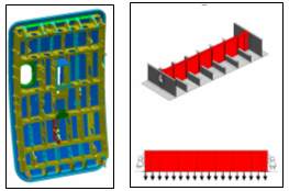
Figure 8. Supporting Beam of an Airplane Door Structure
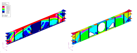
Figure 9. Free-size Result (left); Interpreted Zones of Constant Thicknesses (right)
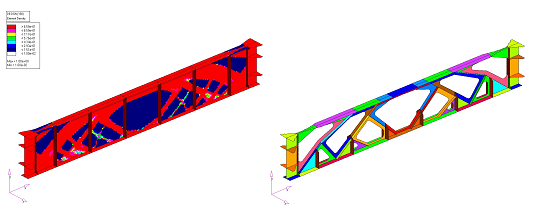
Figure 10. Topology Result (left); Interpreted Zones of Constant Thicknesses (right)
- Maximum deflection of the beam < 3.0 mm
- Maximum von Mises stress in the beam design area < 300 MPa
- Buckling load factors > 1.0

Figure 11. Comparison of Results for Different Deflection Constraints