OS-T: 1930 Generate Flexible Body for use in MotionSolve
In this tutorial you will use an existing finite element model to generate a flexible body for use in MotionSolve. You will run the model in OptiStruct.
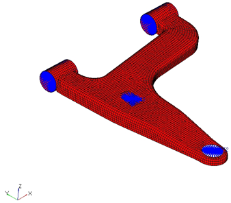
Figure 1.
Launch HyperMesh and Set the OptiStruct User Profile
Open the Model
Set Up the Model
Create Load Collectors to Conduct the Flexible Body Reduction
Modify Load Types
- From the Analysis page, click the load types panel.
- Click .
- Click return.
Create the ASETs
- In the Model Browser, Load Collectors folder, right-click ASET and select Make Current from the context menu.
- From the menu bar, select to open the Constraints panel.
-
Create the first constraint.
-
Select the following degrees of freedom: dof1,
dof2, and dof3.
Tip: Deselect degrees of freedom by right-clicking on a checked (selected) box.
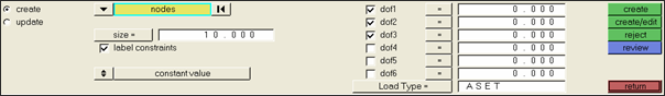
Figure 2.
-
Select the following degrees of freedom: dof1,
dof2, and dof3.
-
Create the second constraint.
- Select the degrees of freedom, dof2 and dof3.
- Using the nodes selector, select the node and the last attachment point of the control arm..
- Click create.
-
Create the third constraint.
- Select the degree of freedom, dof3.
- Using the nodes selector, select the top node in the rigid which would fasten the bottom of the shock assembly to the control arm.
- Click create.
-
Create the fourth constraint.
- Select the degrees of freedom, dof1, dof2, and dof3.
- Using the nodes selector, select the top node in the rigid on the boss to the right.
- Click create.
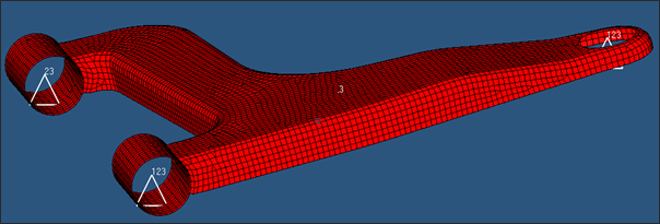
Figure 3. Constraints Applied to the Control Arm Model
Create Subcase
- From the , click to open the Control Cards panel.
- Click GLOBAL_CASE_CONTROL.
- Enable CMSMETH.
- Click CMSMETH and select the CMS load collector.
- Click return to return to the Control Cards panel.
Define Output Request
-
Define the analysis type.
-
Select the options shown below.

Figure 4.
-
Select the options shown below.
-
Create the output control for the component mode synthesis.
-
Select the options shown below.
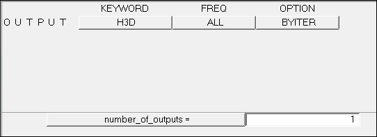
Figure 5.
-
Select the options shown below.
Submit the Job
-
From the Analysis page, click the OptiStruct
panel.

Figure 6. Accessing the OptiStruct Panel
The default files written to the directory are:
- susp_sla.html
- HTML report of the analysis, providing a summary of the problem formulation and the analysis results.
- susp_sla.out
- OptiStruct output file containing specific information on the file setup, the setup of your optimization problem, estimates for the amount of RAM and disk space required for the run, information for each of the optimization iterations, and compute time information. Review this file for warnings and errors.
- susp_sla.h3d
- HyperView binary results file.
- susp_sla.res
- HyperMesh binary results file.
- susp_sla.stat
- Summary, providing CPU information for each step during analysis process.