OS-E: 0825 Multi-Model Optimization (MMO) – Design Scaling with Pattern Repetition in 2 Different C-Clips
Multi-Model Optimization can be used in applications that require optimizing parts of different sizes. This is accomplished by using the SCALE continuation line on linked DTPL and DSIZE entries in the models on which the scaled design is to be applied.
In this example, Topology optimization design variables that are linked between the two models are used (Figure 1). The entire model is the design space made up of PSHELL elements. The Boundary Conditions are different for each model.
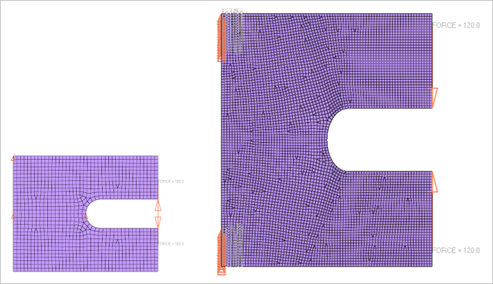
Figure 1. Two C-Clip MMO Models of Different Sizes . with the Entire Model as the Design Space and Different Boundary Conditions
Model Files
Refer to Access the Model Files to download the required model file(s).
The model file used in this example includes:
c_clip_mmo.zip
Model Description
Model 1 and Model 2 are subject to differing boundary conditions. The opposing forces applied to Model 1 try to move the clip arms outward, whereas, in Model 2 the applied forces try to move the arms inward. Additionally, Model 2 is also scaled by 2.0 in the X direction and 3.0 in the Y direction.
- FE Model
- Element Types
- CQUAD4
- MAT1
- Young’s Modulus
- 2.1E5
- Poisson's Ratio
- 0.3
- Initial Density
- 7.9E-9
- Optimization Type
- Topology Optimization
- Responses
- Mass Static Displacement
- Objective
- Minimize Mass
- Constraints
- Static Displacement (2 Grids)
First, set up the individual topology optimization models and test them individually to determine if there are any errors or important warnings during runtime.
ASSIGN,MMO,bc1,c_clip.fem
ASSIGN,MMO,bc2,c_clip.fem
$
BEGIN BULK
$
ENDDATALinked design variables and domains should be identical in all respects (except for the COORD and SCALE continuation lines). The applied design parameters and manufacturing constraints should match in all models. This restriction does not apply to unlinked domains. Additionally, to facilitate internal pattern repetition, a COORD continuation line is required on the corresponding design variable or domain entry (DTPL, DSIZE, and so on). This allows identification of the location and direction of the repeated pattern across linked design domains.
The design domains are linked as:
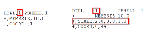
Figure 2.
The SECOND continuation line identifies the scaling factors that are applied to the design.
The COORD continuation line allows the identification of the anchor point and mapping of the design among multiple models. This continuation line is mandatory.
Results
The scaled design has a similar pattern to the original design (Figure 3).
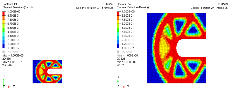
Figure 3. Two C-Clip MMO Models with Scaled Designs