OS-E: 4015 Optimization of MBD System Level Response
MBD system level responses can be displacement, velocity, acceleration, force, or some predefined function of those four quantities. MBD system level responses can be optimized/constrained along with other structural responses of flexible bodies in MBD systems.
Model Files
Refer to Access the Model Files to download the required model file(s).
The model file used in this example includes:
mbdsystemlvlopt.fem
Model Description
The example shown here is intended to minimize the mass of a system. Constraints are imposed on the stress of a flexible body and the velocity of a point. Notable points include the following.
$------|--MID--|--GID--|
MARKER 55      9929617
$------|--RSID-|--RID--|--ITEM-|--MID--|
MBREQM 99 999 VEL 55$------|-------|-------|-------|-------|-------|-------|-------|-------|
DRESP1 3 VELO MBVEL MBREQM TX MIN 999It is not necessary to reference the requests defined by MBREQM/E in the subcase to make the requested responses available for the optimization. RSID (99 in this case) of MBREQM can be an arbitrary positive integer.

Figure 1. A Common Mistake in Defining Shape Change that Involves Change of Joint Locations
In Figure 1, Nodes A and B must remain coincident after applying the shape perturbation.

Figure 2. Correct Way of Defining Shape Change that Involves Change of Joint Locations
Results
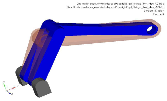
Figure 3. Opaque Orange: Base Line Model; Blue: Optimized Model