Design Interpretation - OSSmooth
A semi-automated design interpretation software, facilitating the recovery of a modified geometry resulting from a structural optimization, for further use in the design process and FEA reanalysis.
OSSmooth is embedded in HyperMesh.
OSSmooth can be used in three different ways: OSSmooth for geometry, FEA topology reanalysis, and FEA topography reanalysis.
- Interpret topology optimization results, creating an iso-density boundary surface (Iso-surface)
- Interpret topography optimization results, creating beads or swags on the design surface
- Recover and smooth geometry resulting from a shape optimization
- Reduce the amount of surface data from a given set of triangular patches by combining smaller patches
- Smooth surface data given as triangular patches
- Preserve component boundaries for multiple design components
- Recover geometry with or without an artificial layer of elements around a non-design space optionally
- Tetramesh Iso-surfaces 'by property'
- Preserve boundary conditions upon geometry recovery to enable quick reanalysis

Figure 1.
Each of the three applications of OSSmooth has a corresponding sub-panel in the OSSmooth panel in HyperMesh. OSSmooth (for geometry) is generally used to recover geometry by interpreting topology, topography, and shape optimization results, while FEA topology and FEA topography are used to generate recovered geometry with boundary conditions for FEA reanalysis.
OSSmooth (for geometry) requires a parameter file (generally has the file extension .oss) to run. This parameter file may be generated from the OSSmooth panel in HyperMesh, or it may be generated manually through a text editor. At the completion of an optimization run, OptiStruct automatically exports an OSSmooth parameter file <prefix>.oss with certain default settings depending on the type of optimization run.
In addition to the parameter file, OSSmooth (for geometry) also requires the input file (<prefix>.fem), the shape file (<prefix>.sh), and/or the grid file (<prefix>.grid) from an OptiStruct run. The grid file <prefix>.grid contains the grid point locations after a topography or shape optimization and is output at the end of a topography or shape optimization run. The shape file, <prefix>.sh, contains the element density information of a topology optimization and is output at the end of a topology optimization run.
FEA topology requires the input model (<prefix>.fem) to be loaded into HyperMesh before running, which is different from OSSmooth (for geometry). It also requires the shape file (<prefix>.sh) generated by a topology optimization. For processing of the non-design elements, two options (Keep smooth narrow layer around and Split all quads) are provided to recover geometry.
The interpreted design from OSSmooth can be exported as a finite element mesh in the Bulk Data format, as IGES surfaces, as a stereolithography file, or as a Config panel Hyper3D file.
Parameter File
The OSSmooth parameter file is composed of a number of parameter statements.
parameter_name arg1,arg2,...,argnThe parameter_name and arguments can be separated either by spaces or commas.
The file is not case sensitive.
Comment lines in the OSSmooth parameter file should start with either '#' or '$'.
input_file- Identifies the files to be interpreted by OSSmooth.
output_file- Name of the file to be output by OSSmooth.
output_code- Identifies the type of output.
units- Defines output units for IGES format. This information gets written to
the header of the IGES file and may be recognized by your CAD system.
- Argument
- Description
- 1 (Default)
- inch
- 2
- mm
- 4
- foot
- 6
- m
- 10
- cm
autobead- Improves the recovered geometry from a topography optimization by
applying automatic geometry creation.
- Argument
- Description
arg1- Operation flag [integer]:
arg2- Threshold value for creating autobead.
arg3- Bead layer [integer]:
isosurface- Generate threshold surface from a topology optimization by applying
automatic geometry creation.
- Argument
- Description
arg1- Operation flag [integer]:
arg2- Type of surface created [integer]:
arg3- Density threshold for creating isosurface.
opti_smoothing- Optimization-based smoothing [Only used if isosurface C2=1].
- Argument
- Description
arg1- Unit-less surface distance coefficient
arg2- Smooth isosurface boundary flag [integer]:
laplacian_smoothing- Laplacian smoothing [Only used if isosurface C2=3].
- Argument
- Description
arg1- Number of iteration for Laplacian smoothing.
arg2- Feature angle threshold in degrees
arg3- Smooth isosurface boundary flag [integer]:
remesh- Remesh autobead surface and/or isosurface flag [integer]:
- Argument
- Description
-
- 0
- Remesh off
- 1
- Remesh on
surface_reduction- Reduces the number of surfaces representing the geometry. Can reduce the
number of surfaces by up to 80%.
- Argument
- Description
arg1- Surface reduction flag [integer]:
arg2- Feature angle threshold in degrees
pure_surface_smoothing- Surface smoothing only.
- Argument
- Description
arg1- Pure surface smoothing flag [integer]:
arg2- Number of iteration [Only used if G1=2]
arg3- Feature angle threshold in degrees [Only used if G1=2]
pure_surface_reduction- Surface reduction only.
- Argument
- Description
arg1- Pure surface reduction flag [integer]:
arg2- Feature angle threshold in degrees
Input File Example
- Parameter
- Description
input_file example- Identifies the root of the input files as example, so OSSmooth will look for the files example.fem, example.grid, and example.sh.
output_fileexample.stl- The resulting output will be example.stl.
output_code 3- The output will be in stereolithography format.
Autobead 1 0.3 1- Topography results will be interpreted using the autobead feature with a threshold value of 30% creating single depth beads.
Isosurface 1 3 0.3- Topology results will be interpreted by creating an iso-density boundary surface with at a density value of 30% and smooth using laplacian smoothing.
laplacian_smoothing 10 30 1- The Laplacian smoothing will run for 10 iterations, consider a feature angle of 30-degrees and including the boundary in the smoothing.
Remesh 1- The two rows of elements around the recovered geometry will be remeshed in an attempt to smooth the mesh transition.
Run OSSmooth
From the HyperMesh OSSmooth Panel
Interpretation of Topology Optimization Results
The purpose of this functionality is to provide an iso-density surface based on the volumetric density information of a topology optimization, which is conducted using OptiStruct.
#general parameters
input_file            mattel
output_file           mattel.stl
output_code           3

#specific parameters
isosurface            1  3  0.300
laplacian_smoothing   10  30.000  1
surface_reduction     1  10.000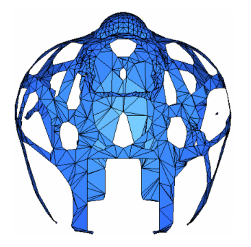
Figure 2. Surface Reconstruction of Shell Element Topology Optimization
The parameter laplacian_smoothing is used for additional smoothing. In most
cases, the threshold surface (isosurface with second argument 0) already
creates a smooth shape. Additional smoothing (isosurface with second argument
3) maintains the topology as suggested by OptiStruct, but
it can deviate from the given density distribution. If this option is used, the maximum and
average smoothing error output by OSSmooth should be checked. The
surface_reduction parameter is used to reduce the number of elements.
Laplacian Smoothing
Used in the smoothing of the results of topology optimization.
laplacian_smoothing statement controls the iteration number of when the
Laplacian smoothing will be performed and the feature angle threshold to
preserve normal discontinuity at corners. One smoothing result is shown
below with the following parameter setting in the OSSmooth parameter
file.#general parameters
input_file surf
output_file surf.stl
output_code 3
isosurface 1 3 0.300
#specific parameters
laplacian_smoothing 10 30.000 1
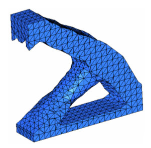
Figure 3. Fix Boundary of Iso-surface
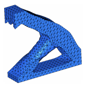
Figure 4. Smooth Boundary of Iso-surface
laplacian_smoothing statement in OSSmooth include:
- The flexibility of controlling the number of smoothing iterations to obtain different degrees of smoothing (possibly a smoothing quality ready for casting). Normally, the iteration number ranges from 5 to 20.
- Smooth boundary of iso-surface with feature angle constrain are seamlessly incorporated into the smoothing process, which is more challenging in a pure CAD system.
Interpretation of Topography Optimization Results
The autobead feature of OSSmooth allows OptiStruct topography optimization results to be interpreted as one or two level beads.
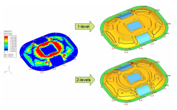
Figure 5. Autobead Interpretation of Topography Optimization Result
#general parameters
input_file            decklid
output_file           decklid.fem
output_code           1

#specific parameters
autobead              1  0.300  1
remesh                1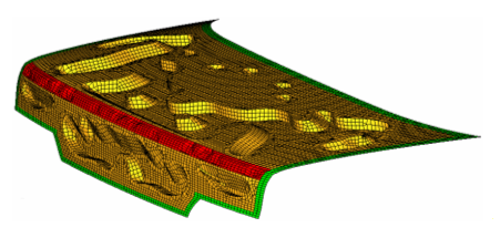
Figure 6. Autobead Result from Topography Optimization
#general parameters
input_file            decklid
output_file           decklid.nas
output_code           1
#specific parameters
autobead              1  0.300  2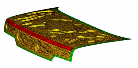
Figure 7. 2-layer Autobead Result from Topography Optimization
Shape Optimization Results, Surface Reduction and Surface Smoothing
OSSmooth may also be used to reduce and smooth surfaces or the surfaces of a domain.
The parameter statements pure_surf_reduction and
pure_surf_smoothing may be used for this purpose.
The file defined by input_file must be in OptiStruct, and OSSmooth can smooth the surface or the surfaces of a domain of the model.
#general parameters
input_file            surf
output_file           surf.stl
output_code           3

#specific parameters
pure_surf_smoothing   2  10  30.000
pure_surf_reduction   1  10.000
FEA Topology for Reanalysis
The purpose of this functionality is to provide an iso-density surface based on the volumetric density information from a topology optimization.
Through tetrameshing for 3D models and inheriting boundary conditions, the results from FEA topology can be used for quick reanalysis.
FEA topology support is available for first and second order shell and solid elements. For 3D models, the recovered iso-surface can be tetrameshed-by-property automatically. FEA topology provides two options for the processing of non-design elements: Keep smooth narrow layer around and Split all quads. Keep smooth narrow layer around will retain an artificial layer of elements around the non-design space in the interpretation and Split all quads will split quad elements in the non-design space, if present, to generate a tetra connection between design and non-design regions. Finally, FEA topology preserves boundary conditions by inheriting them from the original model (<prefix>.fem). Those boundary conditions unattached to nodes/elements after geometry recovery are deleted to ensure reanalysis.
| file | block |
| density threshold | 0.300 |
| Keep smooth narrow layer around | off |
| Split all quads | on |
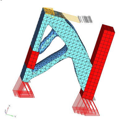
Figure 8. Result of FEA Topology for Reanalysis
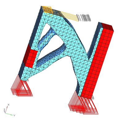
Figure 9. Result of FEA Topology with a Layer of Elements Around Non-design Space
- Tetramesh can be performed by property.
- The flexibility of controlling the number of tetramesh retries by perturbing the density threshold value, in cases where tetramesh sometimes fails.
FEA Topography for Reanalysis
The FEA topography option in OSSmooth allows the results from an OptiStruct topography optimization to be interpreted as one, or two-level beads and recover boundary conditions upon geometry extraction.
| Grid file | brkt |
| Threshold | 0.300 |
| Layers | 1 |
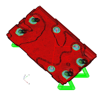
Figure 10. 1-level Autobead Result from FEA Topography
| Grid file | brkt |
| Threshold | 0.300 |
| Layers | 2 |
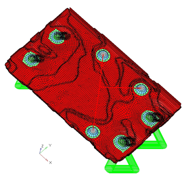
Figure 11. 2-level Autobead Result from FEA Topography