Powertrain Applications
OptiStruct provides industry-leading capabilities and solutions for Powertrain applications. This section aims to highlight OptiStruct features for various applications in the Powertrain industry. Each section consists of a short introduction, followed by the typical Objectives in the field for the corresponding analysis type.
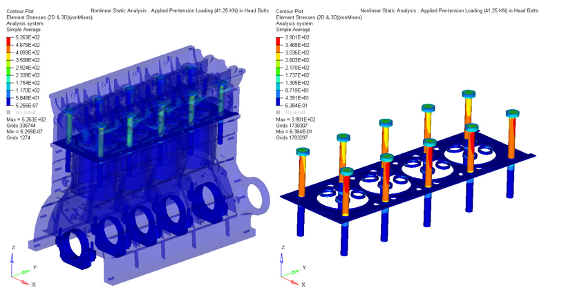
Figure 1. Engine Block Stress Post-processing Example
This document will allow you to understand OptiStruct solution sequences in an application-oriented approach, and effectively try to bridge the gap between powerful powertrain solutions and their adaptation within the industry.
The detailed solution-specific information is available in the corresponding User Guide pages. Here you will look at application-specific information for Powertrain.
Nonlinear Steady-State Heat Transfer Analysis
Nonlinear Steady-State Heat Transfer on the engine block made of the cylinder head, valve guides, valve seats, valves, cylinder head screws, cylinder block, bearing caps, and bedplate.
Theory
Calculate the temperatures in the engine block for subsequent durability analysis.
Best Practices
SimLab can be used to map temperatures and HTC that result from a CFD/combustion analysis onto the mesh used for the Nonlinear Steady-State Heat Transfer Analysis.
Input
- Temperatures and HTC in the water-jacket that result from a CFD analysis
- Temperatures and HTC in the cylinders that can result from a combustion analysis
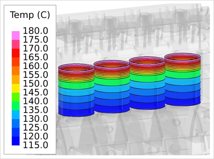
Figure 2. Boundary Conditions in the Cylinders
Output
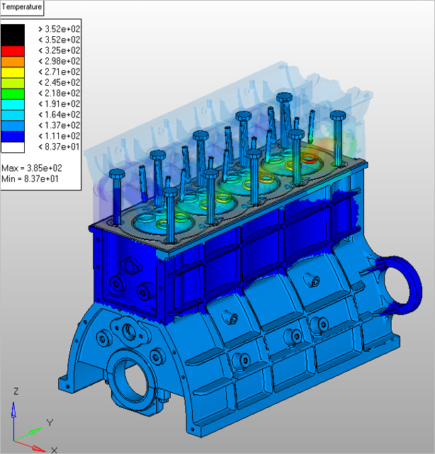
Figure 3. Temperature Results
Thermal Fluid Structure Interaction
Thermal Fluid Structure Interaction Analysis on the engine block made of the cylinder head, valve guides, valve seats, valves, cylinder block, bearing caps and bedplate.
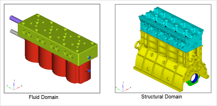
Figure 4. Domain Information
Theory
Evaluate temperatures in the engine block by considering the coupling effect with the fluid domain. These temperatures could then be used as inputs during a subsequent durability analysis.
Calculate pressure drop and the flow uniformity in the fluid domain, i.e. the water jacket.
Input
Initial conditions and boundary conditions for the fluid domain.
Output
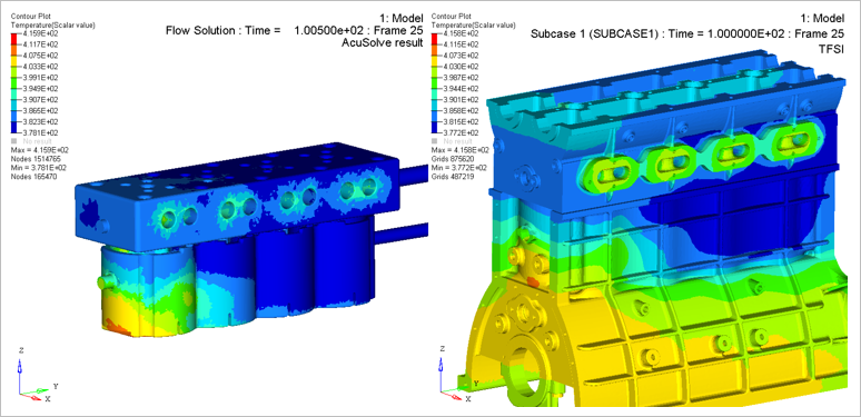
Figure 5. Temperature Results in the Water Jacket and Engine Block
Pressure drop and the flow uniformity in the fluid domain.
Coupled Thermal Structure Analysis
Contact based thermal analysis on the engine block made of the cylinder head, valve guides, valve seats, valves, gasket, cylinder head screws, cylinder block, bearing caps and bedplate. In this model, all parts are in sliding contact or tied contact.
Theory
Evaluate temperatures in the engine block by considering the effect of the contact clearance/pressure on the conductivity. These temperatures could then be used as inputs during a subsequent durability analysis.
Nonlinear static analysis where pretensions are applied in the cylinder head screws. The aim of this subcase is to put all the parts in contact and then model the assembly of the engine block with the ambient temperature.
Contact-based Thermal Analysis where the conductance depends on the contact pressure/clearance. In this subcase the cylinder head bolt pretensions are locked. The objective of this subcase is to model the assembly of the engine blocks with “hot” conditions.
Best Practices
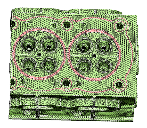
Figure 6. Coincident Mesh
In Figure 6, the gasket mesh have been imprinted onto the mesh of the cylinder head with SimLab to have coincident mesh between these two parts. This has been done to have a better contact modeling in this area.
Input
- Pretension in the cylinder head screws
- Clearance and pressure based conductance values
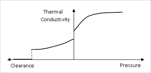
Figure 7. Thermal Conductance Based on Contact Clearance and Pressure - Temperatures and HTC in the water-jacket that result from a CFD analysis
- Temperatures and HTC in the cylinders that can result from a combustion analysis
Output

Figure 8. Contact Pressure Results
Nonlinear Static Analysis
Nonlinear Static Analysis with small deformation and with/without thermal loads. This kind of analysis can be run on most of the PWT components.
Theory
- Distortions
- Bore distortions, bearings out-of-round
- Contact Pressures
- Gasket pressure for sealing
- Relative Displacements
- Openings between the two gearbox cases to estimate the sealing, relative sliding between the engine mount and the engine block.
Best Practices
Figure 9.
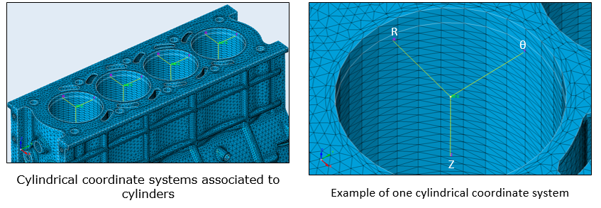
Figure 10. Meshing and Coordinate System
Use the domain decomposition method to reduce time for calculation, especially for the largest models like the model used to calculate bore deformation.
Imprint functionalities available in SimLab can be used to have coincident meshes in contact areas.
Input
Models can involve Thermal loads. In this case, thermal loads that can be constant per components or they may also result from a heat transfer analysis.
- Bolt pretensioning
- N2S and S2S contacts with contact options such as CLEARANCE, ADJUST, SMOOTH
- Gasket material
- Plastic material
- Continue nonlinear solution sequence from a preceding nonlinear subcase (CNTNLSUB)
- Nonlinear Expert System (PARAM,EXPERTNL,YES)
- Restart of Nonlinear Analysis Bore deformation
Output
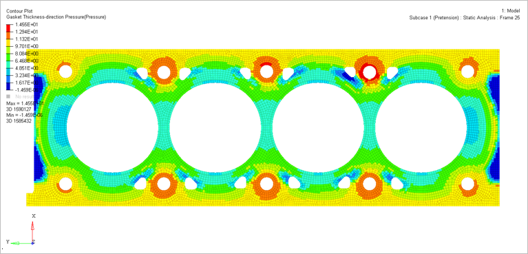
Figure 11. Gasket Pressure Results
Fatigue Analysis
Theory
- Low Cycle Fatigue Analysis (E-N)
Cylinder Head
- High Cycle Fatigue Analysis (S-N)
Engine block, especially the water jacket of the cylinder head, cylinder block, bedplate and bearing caps.
Rotating parts, like the connecting rods and crankshaft.
- Infinite Life (Dang Van)
Engine block, especially the water jacket of the cylinder head, the cylinder block, bedplate and bearing caps.
Rotating parts, like the connecting rods and crankshaft.
Engine mounts.
Gearbox cases.
Best Practices
Use the domain decomposition method to reduce the calculation time for the biggest models.
Fatigue results are only available at element centers. To have results on the external faces of solid components, add shell elements by extracting external faces of these components and calculate fatigue on these shell elements.
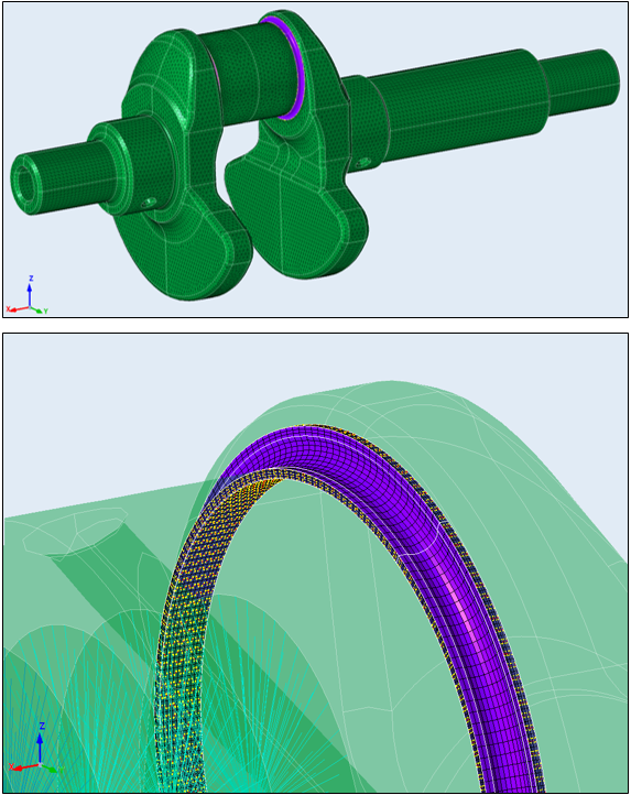
Figure 12. Connection between HEXA and TETRA Elements Made with TIE Contact
Input
Models can involve Thermal loads. In this case, thermal loads that can be constant per components or they may also result from a heat transfer analysis.
Static loads such as the pretension loads, the pressures in the combustion chamber, loads applied on the crankshaft or the bearings that result from a MBD analysis.
Output
- Fatigue Damage and Life
- FOS
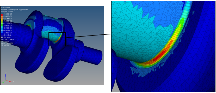
Figure 13. von Mises Stress Results
Noise Vibration and Harshness (NVH) Analysis
Theory
Predict response to modal analysis and frequency-dependent loading of most of PWT components. Depending on the components different approaches are used. Includes Radiated Sound and Equivalent Radiated Power Analysis.
- Single parts or sub-systems
The engine trunk made of the cylinder-head, cylinder block, bedplate and gearbox.
The whole PWT model, as in the engine trunk and all the accessories.
- In these models assemblies can be done through
Bolts modeled with 1D elements.
Bolts modeled with 1D or 3D elements and pretension sections in order to run a prestressed analysis. In this case a Nonlinear Static Analysis has to be performed prior to the NVH analysis.
Sliding contact in order to run a prestressed analysis. In this case a Nonlinear Static Analysis has to be performed prior to the NVH Analysis.
Freeze or Tied contacts
- Typical NVH Analysis that can be performed with OptiStruct
Superelement Generation
Normal Modes
FR analysis
ERP and Radiated Sound Analysis
Best Practices
Use AMSES for large models and/or the number of modes to extract is significant.
Use the domain decomposition method to extract modes with the Lanczos solver on large models.
Input
- Dynamic reduction with CMSMETH
- AMSES
- FASTFR
- Radiated Sound analysis and ERP
- Prestressed normal modes analysis
Output
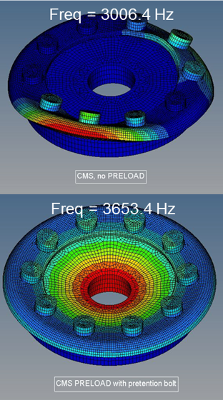
Figure 14. Influence of Frequency on Prestressed Results
Coupling OptiStruct with Third Party Solvers
Theory
OptiStruct can be coupled with a variety of third-party solvers. Here is a quick review of Powertrain-based coupling availability. For detailed information, refer to Create Output for Third Party Software.
Fatigue analysis with FEMFAT, Design Life, FE-Fatigue and FE-SAFE.
Creating the condensed CMS Superelement information for AVL/EXCITE, SIMPACK, ROMAX, ADAMS, Ricardo and Virtual Lab.
Residual run after running AVL EXCITE to recover displacement, velocity, acceleration, ERP, stress, and strain results for interior grids and elements in the CMS Superelement based on the modal participation results from AVL/EXCITE.
Topology Optimization on a Cylinder Block with Bore Distortion Responses
Design space on the external faces of the cylinder block to add ribs.
Setup
Minimize the mass of the cylinder block, bore distortion constraints.
Or,
Minimize bore distortions, constraint on the mass of the cylinder block.
Input
Models can involve Thermal loads. In this case, thermal loads that can be constant per components or they may also result from a heat transfer analysis.
Static loads such as the pretension loads, the pressures in the combustion chamber, loads applied on the crankshaft or the bearings that result from a MBD analysis.
Topology Optimization of the Bedplate
Design space inside and outside the bedplate.
Setup
Minimize the mass of the bedplate, stress constraints and Eigen-frequency constraints.
Input
Models can involve Thermal loads. In this case, thermal loads that can be constant per components or they may also result from a heat transfer analysis.
Static loads such as the pretension loads, the pressures in the combustion chamber, loads applied on the crankshaft or the bearings that result from a MBD analysis.
Output
- One for Nonlinear static analysis.
- One for NVH analysis.
Topology Optimization of the Gearbox Housings
Design space on the external faces of the gearbox housings to add ribs there.
Setup
Minimize the mass of the gearbox, bearings misalignment, engine mount dynamic stiffness, and Eigen-frequency constraints.
Input
Models can involve Thermal loads. In this case, thermal loads that can be constant per components or they may also result from a heat transfer analysis.
Static loads such as the pretension loads, the pressures in the combustion chamber, loads applied on the crankshaft or the bearings that result from a MBD analysis.
Output
- One for Nonlinear static analysis.
- One for NVH analysis.
Shape Optimization on a Cylinder Block with Bore Distortion Responses
Shape or Free Shape variables to modify the geometry of the water jacket.
Setup
Minimize the mass of the cylinder block, bore distortion constraints.
Or,
Minimize bore distortions, constraint on the mass of the cylinder block.
Input
Models can involve Thermal loads. In this case, thermal loads that can be constant per components or they may also result from a heat transfer analysis.
Static loads such as the pretension loads, the pressures in the combustion chamber, loads applied on the crankshaft or the bearings that result from a MBD analysis.
Shape Optimization on a Cylinder Head with Fatigue Responses
Shape or Free Shape variables to modify the geometry of the water jacket.
Setup
Minimize the mass of the cylinder block, constraints on Life or Damage (HCF).
Or,
Maximize Life or Minimize Damage, constraint on the mass of the cylinder block.
Input
Models can involve Thermal loads. In this case, thermal loads that can be constant per components or they may also result from a heat transfer analysis.
Static loads such as the pretension loads, the pressures in the combustion chamber, loads applied on the crankshaft or the bearings that result from a MBD analysis.
Shape Optimization of the Connecting Rod with Fatigue, Contact Pressure and Out-of-Round Responses
Shape or Free Shape variables to modify the geometry of the connecting rod.
Setup
Minimize the mass of the connecting rod.
- Life of Damage (HCF)
- Out-of-round of bearings
- Contact pressure
Input
Models can involve Thermal loads. In this case, thermal loads that can be constant per components or they may also result from a heat transfer analysis.
Static loads such as the pretension loads, the pressures in the combustion chamber, loads applied on the crankshaft or the bearings that result from a MBD analysis.
Topography Optimization of Heat Shields with Frequency and/or ERP Constraints
Topography variables to reinforce the heat shield.
Setup
Minimize ERP, constraint on eigen-frequencies.
Input
Models can involve Thermal loads. In this case, thermal loads that can be constant per components or they may also result from a heat transfer analysis.
Static loads such as the pretension loads, the pressures in the combustion chamber, loads applied on the crankshaft or the bearings that result from a MBD analysis.