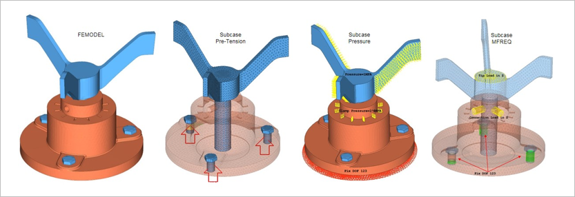
The operational loading involves three steps (or subcases).
In the first subcase a pre-tensioning force of 3.5E3 Newton’s is applied on 3 bolts that
are connected to the flange. In the second subcase a Clamping pressure of 1E4 MPA is applied
on the flange and 1MPA is applied on the folding blades. In the third subcase a tip load is
applied on the flat surface of the blade.
Case 1
Nonlinear Static Analysis
Bolt Pretension
Case 2
Nonlinear Static Analysis
Pressure Load with CNTNLSUB and
STATSUB(PRETENS)
Case 3
Modal Frequency Response Analysis
With STATSUB (PRELOAD)
In Modal Frequency Response Analysis, the modal solution is performed using
AMSES.
FE Model
Bolts
CBEAM
CHEXA
Flange and Blade
CTETRA
The linear material properties are:
MAT1
Young’s Modulus
2.1E5
Poisson's Ratio
0.3
Initial Density
7.8E-9
Results
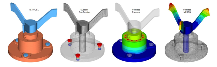
The displacement results on the bolts for subcase 1 and read the .PRET
file and review the results. In Figure 2, observe the
displacement results snapshot from all the 3 subcases.
In subcase 3, the preloading is captured by a geometric stiffness matrix which is based on the stresses of the preloading nonlinear
static subcase 2. In prestressed analysis, this geometric stiffness matrix is augmented with
the original stiffness matrix of the (unloaded) structure.
In this model since there is contact, the contact status can be carried over from the
preloading subcase 2 to the preloaded subcase 3. Figure 2. FE Model, along with the Results from all Three Subcases
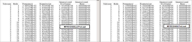
For comparison study, when this example model is run with and without STATSUB
(Pre-Load) in subcase 3, notice the different in the frequencies of the
eigenvector in the .out files. In the Modal Frequency Response Analysis
without Preload you have rigid body modes as the contact between the bolts and the flange
has not been established. Figure 3. Difference in Frequencies of Eigenvector
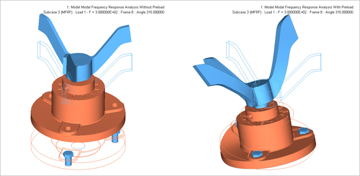
Also, when you plot the MFREQ results at frequency 300Hz, notice the
difference between the mode shape. Figure 4. Modal frequency response plots