OS-E: 2015 Shape and Size Optimization of a Plate in Bending
Shape variables are used in this example to vary both the thickness and the shape of a plate constructed from solid elements. Topography optimization allows discrete areas of the plate to change thickness and/or height, providing a greater range of possible solutions than with shape or size optimization alone.
Model Files
Refer to Access the Model Files to download the required model file(s).
The model file used in this example includes:
sizeandshape.fem
Model Description
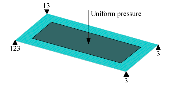
Figure 1. Loads and Constraints for a Plate to be Optimized for Both Shape and Size
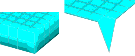
Figure 2. Models Showing the Size and Shape Variations at Maximum Thickness and Height
| DESVAR | 1 | DV001 | 0.25 | 0.0 | 0.25 | |||
| DESVAR | 2 | DV002 | 0.75 | 0.0 | 0.75 | |||
| DTPG | 3 | DVGRID | 1 | |||||
| 3.0 | 60.0 | YES | ||||||
| DTPG | 4 | DVGRID | 2 | |||||
| 3.0 | 60.0 | NO | ||||||
| DVGRID* | 1 | 4 | 0 | 1.0 | ||||
| * | 0.000000000E+00 | 9.9999999748E-07 | 5.0000000000E+00 | |||||
| DVGRID* | 1 | 5 | 0 | 1.0 | ||||
| * | 0.000000000E+00 | 9.9999999748E-07 | 5.0000000000E+00 | |||||
| ... | ||||||||
Entries in fields 15 through 18 are not required because the draw vectors are already defined for each node on the DVGRID cards. A buffer zone is requested for the shape variable that ensures a smooth transition between the constraints and the rest of the structure. Lengthwise symmetry is enforced (the left side of the plate mirrors the right side).
Results
The compliance of the part was minimized with the mass of the part constrained to be below a given value.
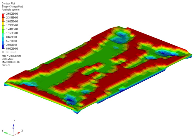
Figure 3. Top View
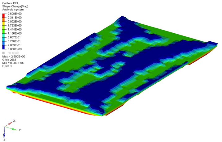
Figure 4. Bottom View
OptiStruct creates a thick rib around the perimeter of the plate, providing a solid foundation for the attachment of the remaining design features. The highest degree of bending occurs at the center of the part, with the largest bending component running in the longitudinal direction. The plate is stiffened in this direction when OptiStruct creates a central rib and a W-shaped reinforcement pattern by raising the thick areas of the plate and lowering the thin areas of the plate. This shape employs the entire structure, not just the parts with ribs.