OS-SL-T: 1060 Free Shape Optimization Analysis of Bracket
This tutorial demonstrates how to solve a linear static analysis for Bracket model and how to optimize the rib shape of the bracket using Free shape optimization analysis.
- Solve a Linear static analysis for the model
- Solve a Free shape Optimization analysis for the model
- View the results
Launch SimLab
Import the Model
Solve Linear Static Analysis
In the following steps, linear static analysis will be defined for the model.
Pressure load will be applied on the face of Sleeve body and Constraints will be applied on the faces of the Bracket body. Tie contact is defined between the sleeve and bracket body. The model setup is solved and the maximum von mises stress value is observed from the analysis.
Define the Solution
-
From the Create Solution dialog, complete the following
and click OK.
- For name, enter BracketAnalysis.
- For Solver type, select OptiStruct.
- For Solution type, select Linear Static.
- For Select bodies, select all the bodies of the model.
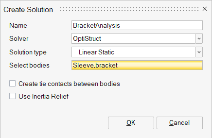
Figure 1. Create Solution
Assign Property to Bodies
In this step, you will assign the Cast Iron property for the Carrier and Cover bodies and the Steel property for the Bolts.
Since SimLab has default materials defined, there is no need to define materials.
-
In the modeling window, select the Snap body.
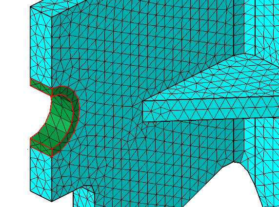
Figure 2. Select Snap Body -
In the Analysis Property dialog, complete the following
and click Apply.
- For Name, enter Sleeve.
- For Entity, select Solid.
- For Type, select Solid.
- For Behavior, select Isotropic.
- For Material, select Steel.
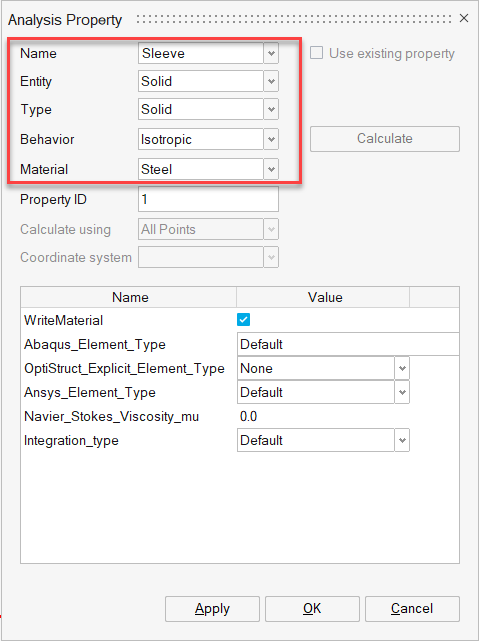
Figure 3. Property Defined for Sleeve Body -
In the modeling window, select the Bracket body.
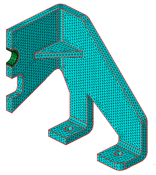
Figure 4. Select Bracket Body -
In the Analysis Property dialog, complete the following
and click OK.
- For Name, enter Bracket.
- For Entity, select Solid.
- For Type, select Solid.
- For Behavior, select Isotropic.
- For Material, select Steel.

Figure 5. Property Defined for Bracket Body
Pressure Load on Sleeve Face
-
In the modeling window, select the Sleeve body.
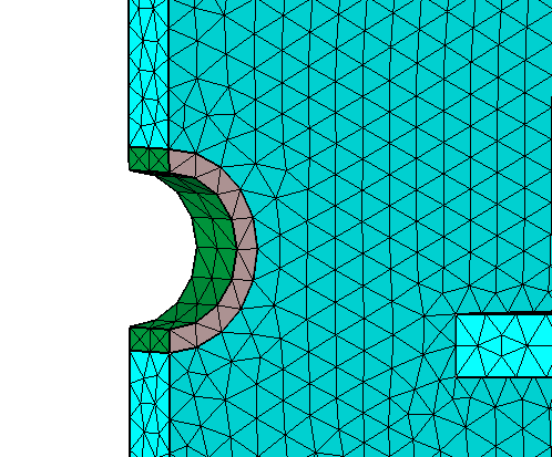
Figure 6. Select Sleeve Body -
In the Pressure dialog, click OK.
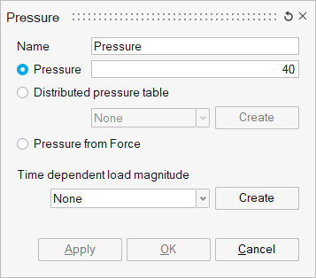
Figure 7. Pressure Load Input
Fixed Constraint on Bolt Holes
In this step, you will create fixed constraints on the bolt holes of the bracket body.
-
Enable the X, Y, and
Z checkboxes under Displacement.
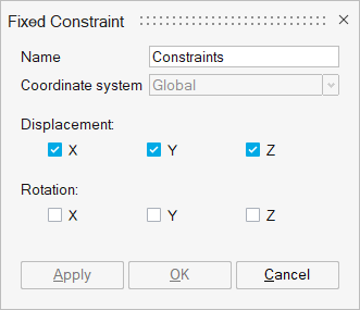
Figure 8. Create Fixed Constraint -
In the modeling window, select the bolt hole faces of
the Bracket body.
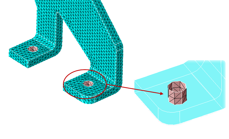
Figure 9. Select Bolt Holes
Symmetry Constraints on Side Faces
Since the Bracket is symmetrical, fixed constraints are defined on the end faces of the model to represent the symmetry.
-
Enable the X checkbox under Displacement.
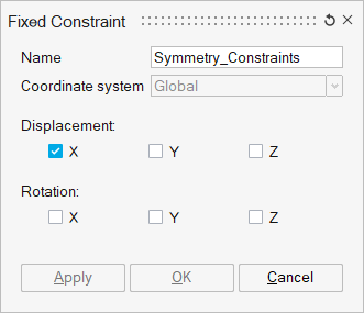
Figure 10. Create Fixed Constraint -
In the modeling window, select the side faces of the
model.
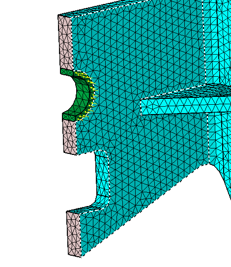
Figure 11. Select Side Faces
Contact Between Sleeve and Bracket Body
-
In the modeling window, select the
Bracket body for Main body.
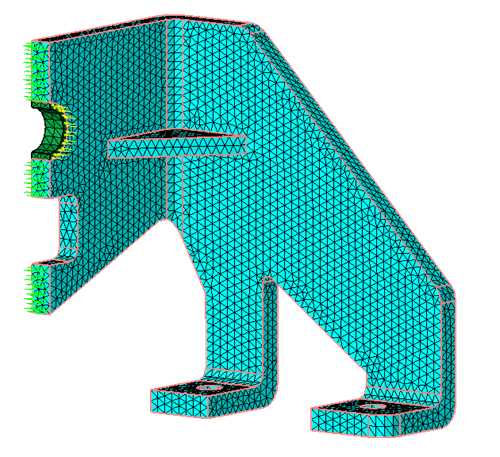
Figure 12. Main Face Inputs for Contact Creation -
In the modeling window, select the
Sleeve body for Secondary body.
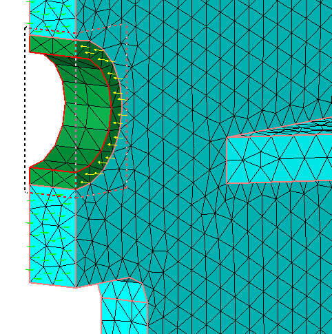
Figure 13. Secondary Face Inputs for Contact Creation -
In the Define Contact dialog, define the following
parameters and click OK.
- For Trim, select Secondary and Main.
- For Tolerance, enter 0.1.
- For Face type, select Cylindrical.
- For Contact Type, select TIE.
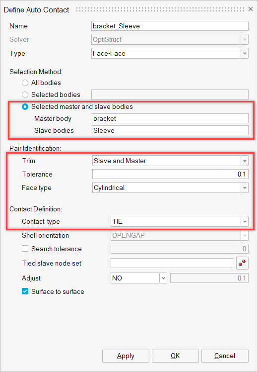
Figure 14. Define Tie Contact Between Sleeve and Bracket Body
Solve the Solution
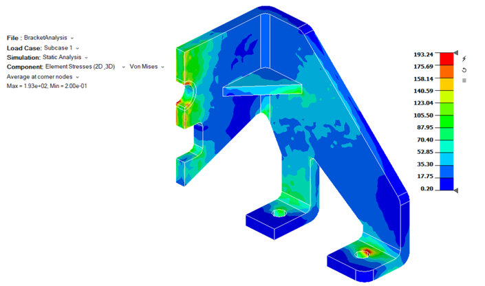
Figure 15. Von Mises Stress Example
Solve Free Shape Optimization
In the following steps, the shape of the rib will be optimized using the Free shape optimization method to maximize the displacement and constraint the von-mises stress.
Define Optimization
-
Select Free shape for method and click
OK.
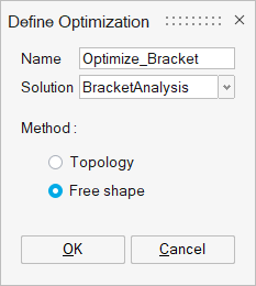
Figure 16. Define Free Shape Optimization Solution
Create Design Space
-
For Bodies/Faces/Nodes, select the face of the Rib in
the modeling window and click Apply.
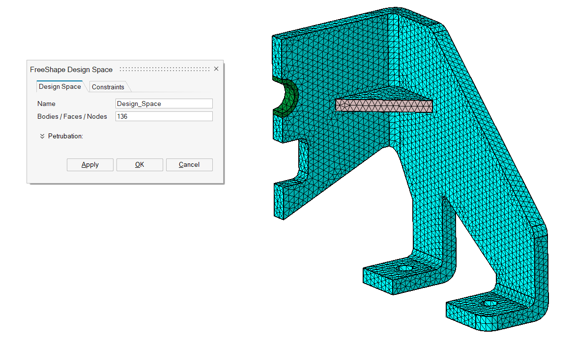
Figure 17. Define Design Space for Optimization
Create Design Space Constraints
-
Define the axis for the Pattern Constraint.
-
In the Define Axis dialog, verify the 2
Nodes checkbox is enabled.
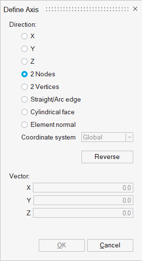
Figure 18. Define Pattern Constraint for Design Space -
In the modeling window, pick two nodes of the
rib face.
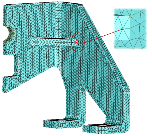
Figure 19. Define Direction for Pattern Constraints
-
In the Define Axis dialog, verify the 2
Nodes checkbox is enabled.
-
In the FreeShape Design Space dialog, click
 under Grid Constraint.
-
For Face, select the rib face in the modeling window.
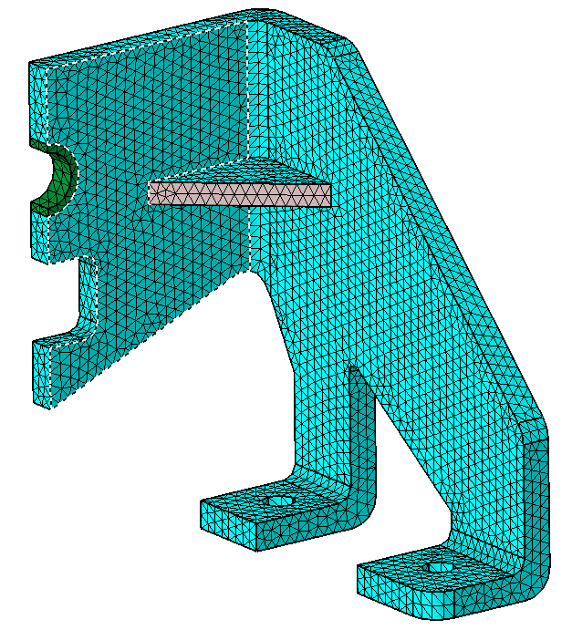
Figure 20. Select Rib Face -
Create Grid constraint on the supporting face of the bracket.
-
In the FreeShape Design Space dialog, click under Grid Constraint.
-
For Face, select the supporting faces in the modeling window.
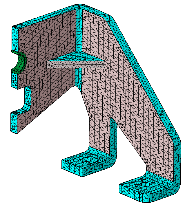
Figure 21. Select Supporting Faces -
For Type, select Fixed.
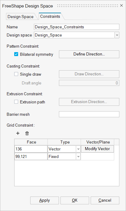
Figure 22. Define Grid Constraint for Supporting Faces of Bracket Body
-
In the FreeShape Design Space dialog, click
Create Responses
In this step, you will define displacement and stress response.
You will also define the limit for the stress response.
-
Define displacement response.
-
For Response type, select Static
displacement.
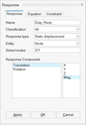
Figure 23. Define Displacement Response -
In the modeling window, select the corner node
of the Bracket body.
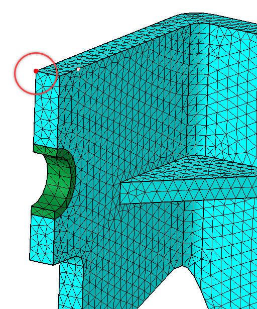
Figure 24. Select Corner Node
-
For Response type, select Static
displacement.
-
Define stress response.
-
In the modeling window, select the bracket
body.
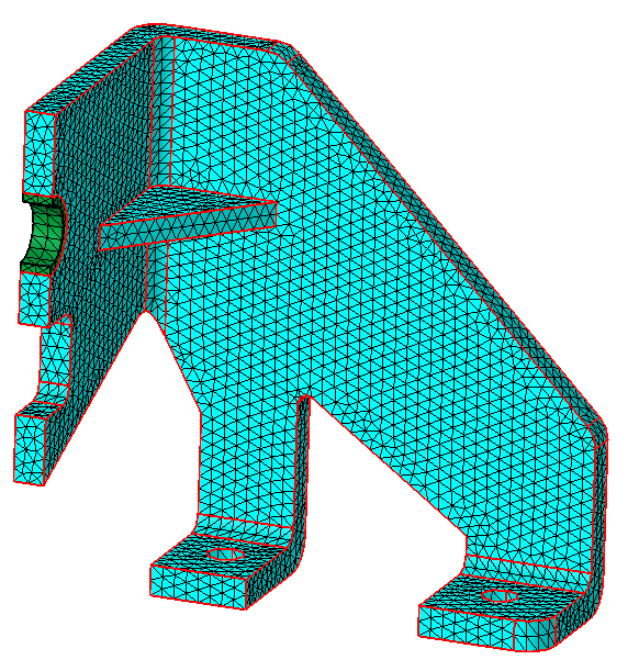
Figure 25. Select Bracket Body -
For Response Component, select Von Mises.
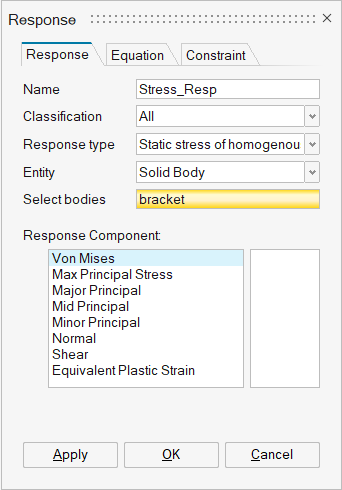
Figure 26. Define Stress Response
-
In the modeling window, select the bracket
body.
-
Set the limit for the Stress response.
- In the Response dialog, click the Constraint tab.
- For Name, enter Stress_Resp_Constraint.
- For Response, select Stress_Resp.
- Enable the Upper bound checkbox and enter 200.
- Click OK.
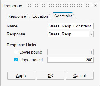
Figure 27. Define Constraint for Stress Response
Define Objective
The objective of this optimization is to maximize the displacement.
-
For Response, select Disp_Resp and click
OK.
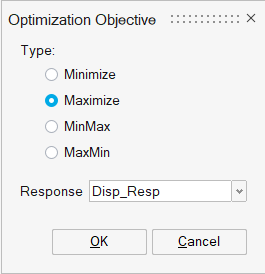
Figure 28. Define Objective
Solve and View Results
Solve the Solution
Interpret the Results
- In the Animation toolbar, click the Deformation Settings icon and enter 1 for Auto scale.
- For Deformation, select XYZ.
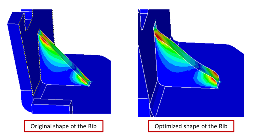
Figure 29. Difference Between Original and Optimized Shape of the Rib