OS-E: 0600 Steady-state Thermal Analysis with Convection Loading of a Structure with
Insulator
Heat sink with fins are commonly used in engineering applications to dissipate heat.
The 3D geometry of an aluminum heat sink designed for cooling. The cross-sectional view of a
furnace constructed from two materials.
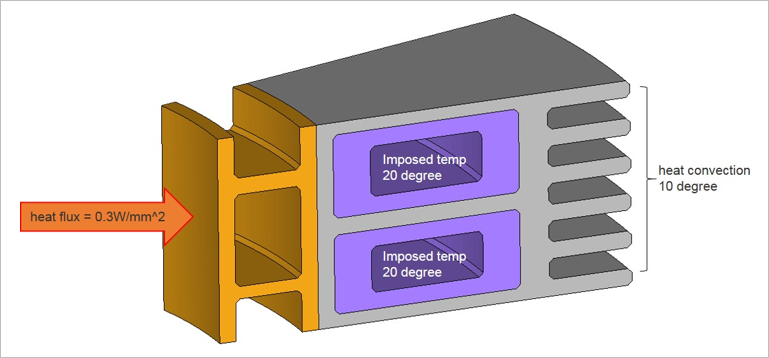
The inner part is made of copper and the outer heat sink wall is made of aluminum. The
outer heat sink wall comes into contact with the ambient air and heat convection.
The Finite element model consists of three different materials.
Loads and boundary condition are explained in Figure 1.
FE Model
Element Types
CHEXA
The MAT4 linear material properties are:
Aluminum
Thermal Conductivity
0.2
Heat Capacity Per Unit Mass
921.0
Density
2.9E-9
Free Convection Heat Transfer Coefficient
0.001
Cooper
Thermal Conductivity
0.5
Heat Capacity Per Unit Mass
385.0
Density
6.0E-9
Free Convection Heat Transfer Coefficient
0.0037
For Insulator
Thermal Conductivity
0.001
Heat Capacity Per Unit Mass
410.0
Density
1.02E-9
Free Convection Heat Transfer Coefficient
0.00017
Results
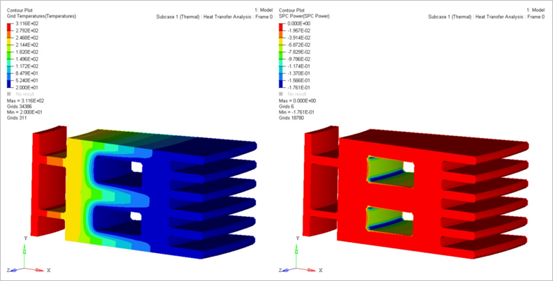
Grid temperature and SPC power is shown in Figure 2.
SPC power is a measure of energy flowing in and out of the
structure. Figure 2. Grid Temperature and SPC Power Contour
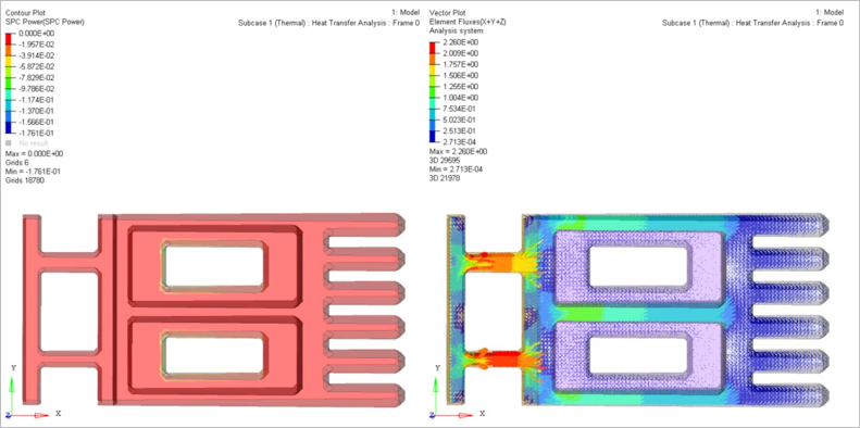
SPC power and Element Flux is shown in Figure 3. Figure 3. SPC Power and Element Flux Contour