OS-T: 8000 Trim Analysis using the Stick Model of an Aircraft Wing
This tutorial demonstrates trim analysis using the stick model of a simple aircraft wing.
Stick models are generally used to simplify the representation of an aircraft for aeroelastic analysis.
Preprocessing is done using Altair HyperWorks in the OptiStruct user profile. A structural stick model with existing data is used as a base model and this tutorial demonstrates the creation of entities in the Aeroelasticity domain.
- Create Panels (CAERO1)
- Create interpolation splines (SPLINE2)
- Create rigid body motions for aeroelastic TRIM variables (AESTAT)
- Define TRIM variables
- Submit the job
- View the results
Launch HyperWorks and Import the Model
-
In the Solver Import Options dialog, for Reader select
OptiStruct.
The OptiStruct user profile loads. The functionality of HyperWorks is paired down to the appropriate template, macro menu, and import reader to create models in OptiStruct.
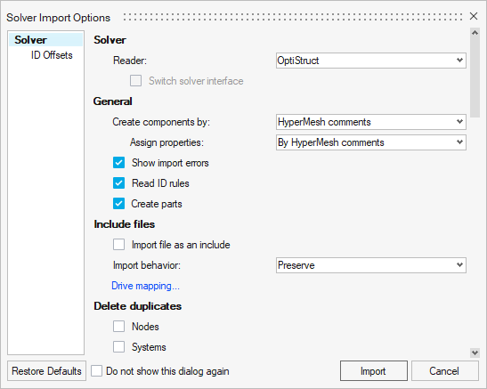 Figure 1. Import Base Model in HyperWorks
 -
Click Import.
The base structural stick model is loaded into HyperWorks. The model is comprised of CBAR elements.
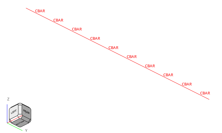
Figure 2. Base Structural Model of an Aircraft Wing Stick Model
Open the Aeroelasticity Browser
The Aeroelasticity Browser is useful for upcoming tasks in this tutorial.
-
On the Aeroelasticity ribbon, hover over any tool group
and click the satellite icon that appears.
The Aeroelasticity Browser opens.
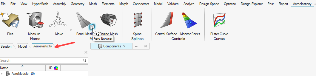
Figure 3. Access the Aeroelasticity Browser
Set Up the Model
Create AEROS Entry
In this step, basic/reference parameters for the simulation are defined through AEROS.
-
For REFS (Reference wing area), enter 0.055.
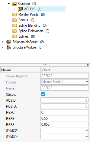
Figure 4. AEROS Definition
Create Grid Points around the Stick Model
Since the base structural model is a stick representation, grid points are created around the stick model as corner points of the panel mesh.
-
On the Geometry ribbon, Points tool group, click the Create Points
and Nodes tool.

Figure 5. -
In the X, Y, and Z grid coordinate fields, enter 0.0.
Press Enter to confirm.
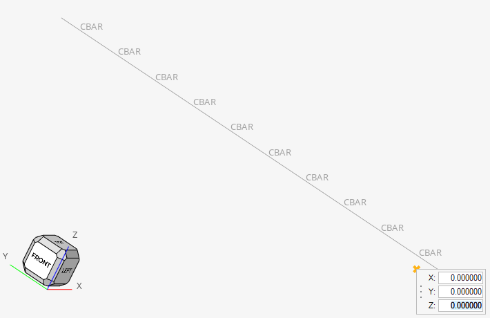
Figure 6. Create Grid Points -
Right click and exit the tool.
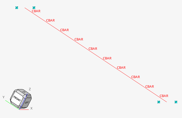
Figure 7. Grid Points around Stick Model
Create Aeroelasticity Panels
The CAERO1 entry is used to create aeroelasticity panel mesh in the base structural model.
-
On the Aeroelasticity ribbon, Aero Meshing tool group,
click the Panel Mesh tool.

Figure 8. -
Select the Transparent check box.
The points surrounding the structural model are displayed.
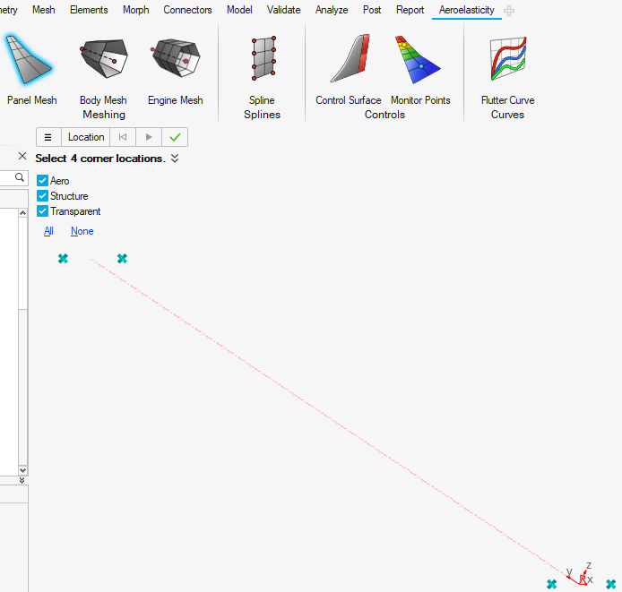
Figure 9. Open Panel Mesh Tool -
Select the end points of the CAERO1 panel mesh so that node
1 and node 4 are along the span direction and node 1 and 2 are along the chord
direction. For more information, refer to CAERO1.
Figure 10 shows the correct selection order.
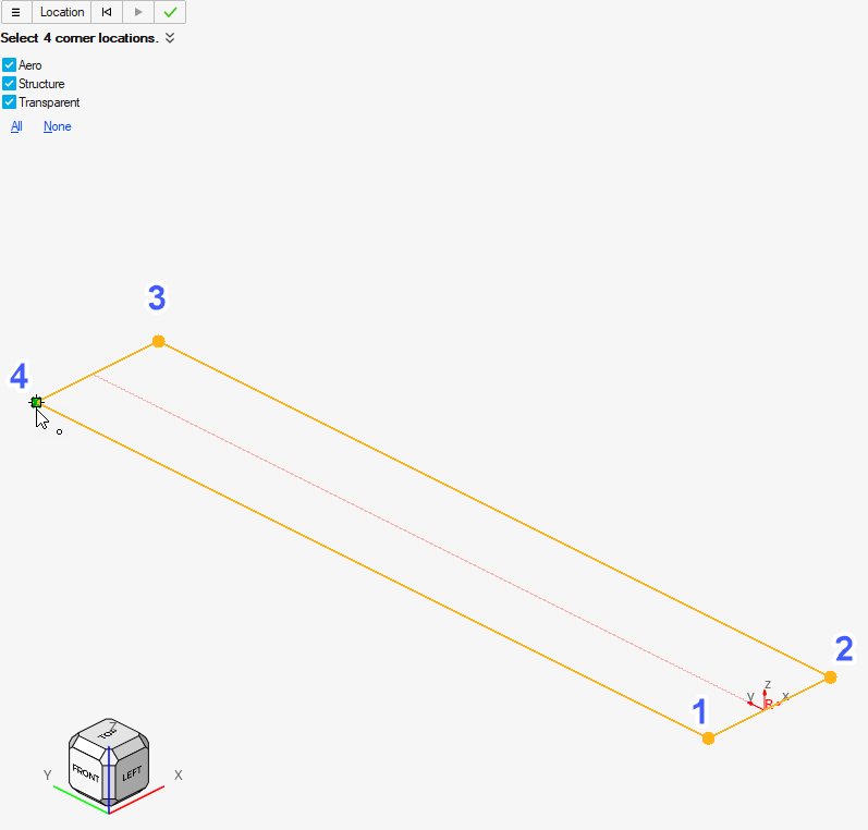
Figure 10. Grid Point Selection for CAERO1 Definition -
Click
 .
.
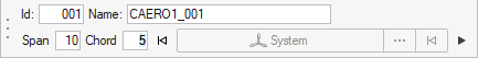
Figure 11. Specify Span and Chord Values in CAERO1 DefinitionThe panel mesh is created.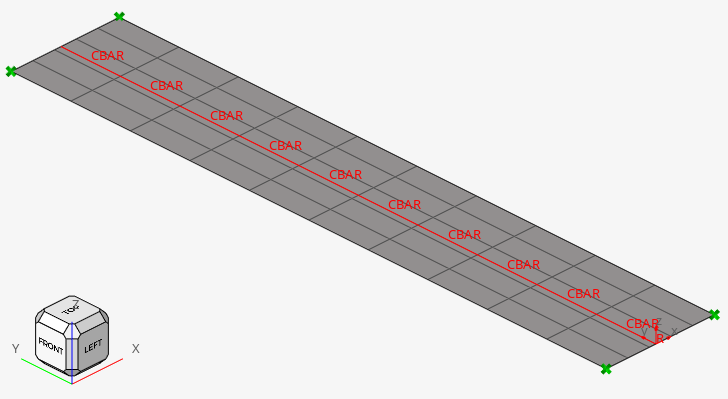
Figure 12. Aeroelastic Panel Mesh for the Problem
Create Interpolation SPLINES
In this step, a SPLINE2 entry is created for interpolating motion and/or forces between the aeroelastic and structural domain. The SPLINE2 entry refers to the panels (aeroelastic domain), a node-set (structural domain) and the corresponding CAERO1 entry. The node-set for the structural domain is already available in the base model.
-
On the Aeroelasticity ribbon, click the
Spline tool.

Figure 13.The SPLINE2 creation tool opens. -
Click the
 icon.
icon.
-
For Spline type, select Linear_Spline_2 from the
drop-down menu.
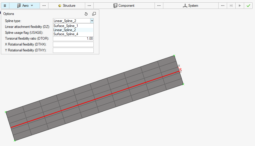
Figure 14. Selection of Linear Spline (SPLINE2) -
Reference the aero panels.
-
In the Aero drop-down menu, select
Elements.
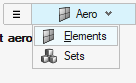
Figure 15. Element Based Selection in Aero Domain -
On the model, select the aero panels.
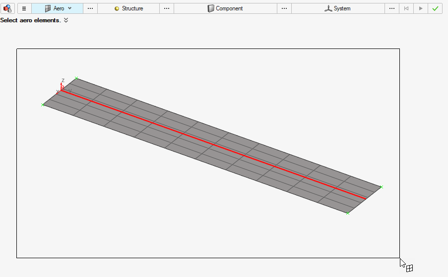
Figure 16. Selection of Aero Panels on Model
-
In the Aero drop-down menu, select
Elements.
-
Reference the node-set.
-
In the Structure drop-down menu, select
Sets.
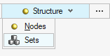
Figure 17. Set Based Selection in Structural Domain -
Click
 .
.
-
In the Advanced selection dialog, select
SET1.
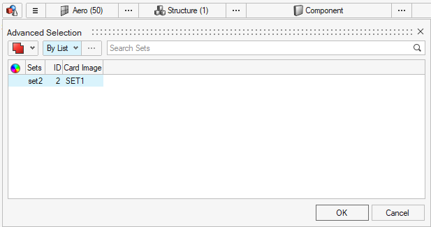
Figure 18. Selection of Structural Node Set
-
In the Structure drop-down menu, select
Sets.
-
Reference the CAERO1.
-
Next to Component, click .
-
In the dialog, select the CAERO1 previously
created.
Figure 19. Selection of CAERO1 Entry
-
Next to Component, click
-
In the microdialog that appears, enter a name of your choice. In this tutorial
the name is SPLINE2.
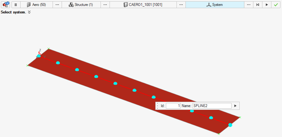
Figure 20. Name SPLINE2 Entry -
Click .
The spline is shown under the Splines section on the Aeroelasticity browser.
-
Reference the existing coordinate system.
-
For CID, click and select .
- In the dialog, select the existing coordinate system.
-
For CID, click and select
-
Specify other parameters as shown in Figure 21.
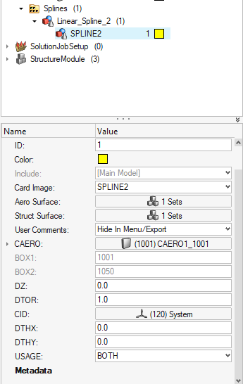
Figure 21. SPLINE2 Definition
Create AESTAT Entry
The AESTAT entry specifies rigid body motions which are used as trim variables in the aeroelastic analysis. This is later referenced in the TRIM Bulk Data Entry.
Define TRIM Entry
In this step, the Mach number, Dynamic pressure, and constraint values for the aerodynamic trim variables are defined.
- In the Aeroelasticity Browser, right-click on Aero Loads and select .
- For Name, enter TRIM ANGLEA 0.1 RAD1.
- For Q (Dynamic pressure), enter 1500.0.
- For NUM_LABEL, enter 1.
-
Reference AESTAT.
-
Under TRIM1, for LABEL, click and select .
-
In the Advanced Selection dialog, choose
ANGLEA_AESTAT.
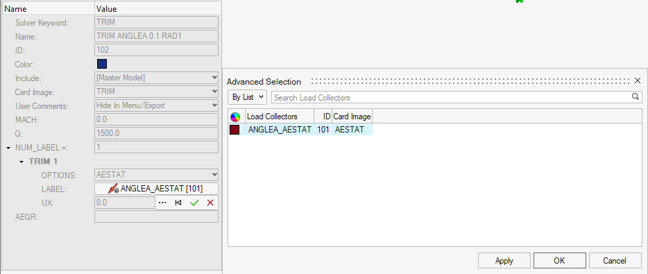
Figure 22. Reference AESTAT in the TRIM Entry
-
Under TRIM1, for LABEL, click and select
Reference the TRIM Entry in the Subcase
In this step, the TRIM entry is referenced in the subcase.
- In the Aeroelasticity Browser, expand and click the TRIM_ANALYSIS subcase.
-
Reference the TRIM entry.
-
For TRIM, click and select .
-
In the Advanced Selection dialog, choose TRIM ANGLEA 0.1
RAD1.
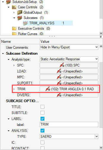
Figure 23.
-
For TRIM, click and select
- Under SUBCASE OPTIONS, for Analysis TYPE, select SAERO from the drop-down menu.
Export the Input File
In this step, the input file is exported to the working directory. This file is later solved using OptiStruct as the solver.
Submit the Job
The Altair Compute Console (ACC) is used to submit the job.
-
For Input file, use
 to browse your working directory for the desired
file.
to browse your working directory for the desired
file.
-
For Options, click
 .
.
- In the Select Solver Options dialog, click the -nt check box.
- Enter 4 for the argument.
- Click OK.
- Click the -out check box.
-
Click Run.
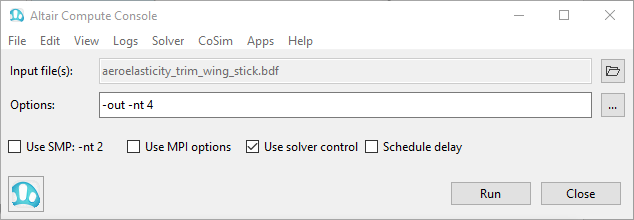 Figure 24. Altair Compute Console
If the job is successful, the new results files should be in the working directory. If any errors are present, look in the aeroelasticity_trim_wing_stick.out file for error messages that could help debug the input deck.
View the Contour Plot
The following steps describe how to review the results in HyperView.
HyperView is a complete post-processing and visualization environment for finite element analysis (FEA), multi-body system simulation, video, and engineering data.
-
In HyperView, click the Contour panel button
 .
.
-
Click Apply.
The resulting contour represents the displacement field for the aeroelastic trim analysis.
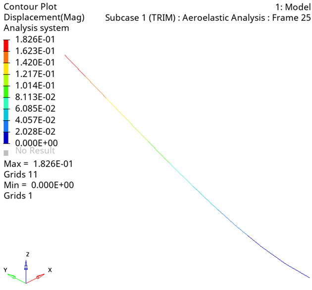
Figure 25. Displacement Contour Plot of Wing Stick Model