Actuators
Use the Actuators tool to apply an actuator to features or connected parts.
Actuators drive parts in a translational manner, and can be defined in terms of displacement, velocity, acceleration, or force. Inputs can be based on time or the state of a variable object (motor, actuator, system, or measure).
Click the ![]() satellite icon that appears when you hover over the Actuators tool to view a list of all
actuators in your model.
satellite icon that appears when you hover over the Actuators tool to view a list of all
actuators in your model.
Add Actuators to Connected Parts
It's best to connect parts with joints before applying actuators. The connected parts option on the guide bar scans the model for cylindrical or translational joints that are suitable for an actuator.
-
In the microdialog, select an input:
- Time Dependent
 : Make the actuator dependent on time.
 - State Dependent
 : Make the actuator dependent on the state
of a variable object (motor, actuator, system, or measure). You can then
represent input relationships such as Torque vs. Speed, Force vs. Angle,
or Force vs. Distance. For details, see State Dependent Inputs.
: Make the actuator dependent on the state
of a variable object (motor, actuator, system, or measure). You can then
represent input relationships such as Torque vs. Speed, Force vs. Angle,
or Force vs. Distance. For details, see State Dependent Inputs.
- Time Dependent
-
Enter a magnitude in the text field for the displacement, velocity,
acceleration, or force. Click the
 icon to calculate the default displacement.
Add Actuators to Features
An actuator is defined by a shaft and a base. The first click positions the shaft, and the second positions the base.
-
Enter a magnitude for the displacement, velocity, acceleration, or force. Click
the icon to
calculate the default displacement.
- An option to hide all actuators is available in the right-click context menu. In some models hiding all actuators may improve performance of the animation.
- You can select the same hole or surface twice, in which case the second click is interpreted as reacting against ground. For a sliding pin through a single part, the actuator will be attached between the part and the ground.
- You can change the appearance of the actuator shaft and base using the Appearance properties in the Property Editor.
- If you intend to rigidly lock an actuator or motor that is of type=Velocity, you should disable the controller. If you do not do so, then you will need to adjust the PID gains in order to prevent (or at least minimize) movement.
- Suppress/Unsuppress an actuator to understand its effect on your model. On the actuator, right-click and select Suppress. From the Model Browser or Table, right-click and select Unsuppress.
State Dependent Inputs
You can assign inputs to motors and actuators that are dependent on the state of motors, actuators, systems, and measures. Example input types include Torque vs. Speed, Force vs. Angle, and Force vs. Distance.
Example: Force Applied to Blade as a Function of Drive Gear Rotation Cycle of 3600
-
Make the motor or actuator dependent on a variable object:
-
In the microdialog, click
 , and then select the option.
-
Click
 .
.
-
In the microdialog, click
-
In the Profile Editor, specify the variable range or cycle over which the input
function will be applied.
-
In the microdialog click
 Profile Editor.
- Specify the variable range or cycle over which the input function will be applied:
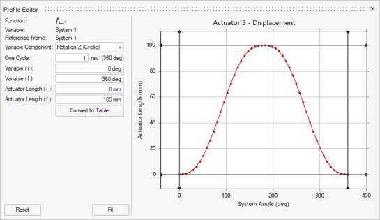
Option Description Function Select a profile function. Supported functions include: - Step
- Step Dwell Step
- Single Wave
- Impulse
- Table
Variable The independent variable object (system, measure, motor, or actuator). Reference Frame The reference frame used by the variable component. Variable Component The independent variable component output that the state dependent object will monitor. Use the dropdown menu to access to the library of functions. 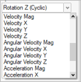
One Cycle (for cyclic rotations) Specify the cycle range within which the V(i) and V(f) values fall. For example, a 4-stroke piston engine will experience combustion force every 2 revolutions (or 720 degrees) of the crankshaft. Variable (i) Enter the initial value of the independent variable object (system, measure, motor, or actuator). Variable (f) Enter the final value of the independent variable object (system, measure, motor, or actuator). [Variable Object] Force (i) Enter the initial value of the state dependent object. [Variable Object] Force (f) Enter the final value of the state dependent object. -
In the microdialog click
Microdialog Options
Use the options in the microdialog to edit the behavior and appearance of an actuator.
Click the ![]() to view advanced
options.
to view advanced
options.
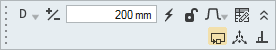
Figure 1. Actuators Microdialog
- Type
- Use the D, V, A, F drop-down menu on the microdialog to change the type of actuator. Options are displacement, velocity, acceleration, and force.
- Reverse Direction
- Use the +/- button to reverse the actuator's direction of translation, as indicated by the arrow.
- Set Displacement/Velocity/Acceleration
- Enter a magnitude for the displacement, velocity, acceleration, or force. Click the
 icon to calculate the default displacement.Note: If you enter zero for the magnitude, the actuator will be locked and most of the options in the microdialog and Profile Editor will become uneditable.
 - Lock the Actuator
- Lock the actuator to stop it from translating. This is useful for debugging.
- Time
- Make the actuator profile dependent on time.
- Independent Variable
- Make the actuator profile dependent on a selected variable.
- Select Independent Variable
- In the modeling window, select a measure, system, actuator, or motor to make it the independent variable.
- Profile Function
- Use the profile function to change how the shaft translates as time elapses. Examples include step, single wave, or oscillating.
- Edit the Profile Function
- Open the Profile Editor, which allows you to edit profile data and view it in an interactive chart.
- Use Controller
- A controller is used to achieve the target displacement or velocity. If you disable the controller it will use the target profile directly, which could result in excessive deformations or other warnings.
- Move Actuator
- Click to open the Move tool, allowing you to reposition the actuator.
- Align shaft with connection
- Click to align the actuator so it is perpendicular to the connection to which it was applied.
Actuator Properties
Refine the behavior and appearance of actuators using the properties available in the Property Editor (F3).
- Rotate with Part
- Enables an actuator to either rotate (or not rotate) with the shaft part.
- Maintain Coaxiality
- Enable this property to create an implicit joint. There are two joint options for the coaxial joint type: cylindrical and translational.
- Base Scale
- Use to change the appearance of the motor shaft and base. The Base Scale property allows you to change the size of the motor; enter a value between 0.5 and 2.0.
- Shaft Radius
- Use to adjust the overall size of the shaft. This property is not available for motors applied to holes.
Actuators Table
The Actuators table lists all of the actuators in your model and allows you to edit various attributes.
Location: Actuators tool, satellite icon ![]()
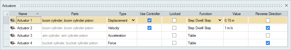
Figure 2. Actuators Table
| To | Do this |
|---|---|
| Rename a actuator | Select the cell in the table and then click again to make the field editable. |
| Change the type | Select the cell in the table and then select a different option from the list. |
| Sort a column | Click the column header. Click repeatedly to toggle between ascending and descending order. |
| Add or remove columns | Right-click on a column header. |
Shortcuts
| To | Do this |
|---|---|
| Deselect a feature | Hold down the Ctrl key and left-click a selected (red) hole or surface. |
| Exit the tool | Right-click and mouse through the check mark to exit, or double-right-click. |