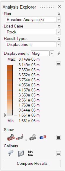
View Linear Static Results
Finite element analysis produces a number of different result types for each load case depending on the type of analysis that was run and what options where chosen. Select a run, load case, and result type in the Analysis Explorer to view the results of a linear static analysis.
-
On the Structures ribbon, select the Show Analysis
Results tool to open the Analysis Explorer.

-
The result is displayed in the modeling window. Use the results slider to
change how the results are displayed.
- To change the upper or lower bound for the results slider, click on the bound and enter a new value.
- To filter the results so that areas on the model with results greater than a specified value are masked, click and drag the arrow on the results slider.
- To change the legend colors used to show the displacement, click the
 icon next to the results slider
and select Legend Colors.
icon next to the results slider
and select Legend Colors.
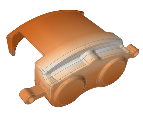
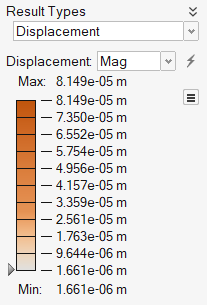
Displacement
The displacement result type shows how much your model displaces or deflects when loads and supports are applied. The areas of the model that are the darkest orange have the most displacement.
- Order of magnitude
- Does the magnitude of the displacement make sense? If a component that is 100 mm long has a displacement of 1000 mm, this indicates that either the load magnitudes are incorrect or the model is not properly supported. This may also be caused by incorrect material properties.
- Shape of the deformation
- By animating the model for each load, you can check that the structure is deflecting in a logical way. Unusual behavior is usually the result of incorrectly applied loads and/or supports.
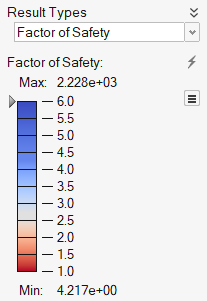
Factor of Safety
The factor of safety result type shows which areas of a model are in danger of yielding due to stress. The factor of safety for each part's material is taken into account when determining the overall factor of safety for the model and is calculated as follows:
factor of safety = material yield stress ÷ von Mises stress.
A factor of safety of 1.0 or lower means your part may fail. By default, areas that are approaching a minimum safety factor of 1.0 are shown in red and indicate where the part is most likely to fail.
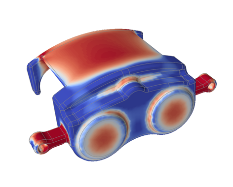
The accuracy of a factor of safety analysis depends on having accurate loads, materials, and models as input. There is no definitive factor of safety that is suitable for all applications.
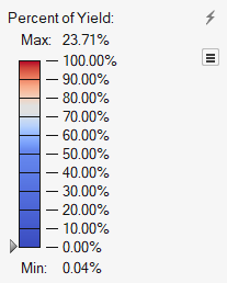
Percent of Yield
The percent of yield result type shows which areas of a model are in danger of yielding due to stress. It is essentially the inverse of factor of safety and is expressed as a percentage. The percent of yield for each part's material is taken into account when calculating the overall percent of yield for the model and is calculated as follows:
percent of yield = (von Mises stress ÷ material yield stress) x 100
A percent of yield of 100% means your part may fail. By default, areas that are approaching a percent of yield of 100% are shown in red and indicate where the part is most likely to fail.

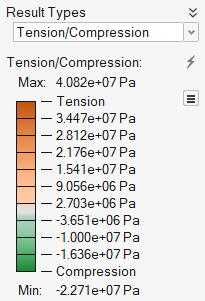
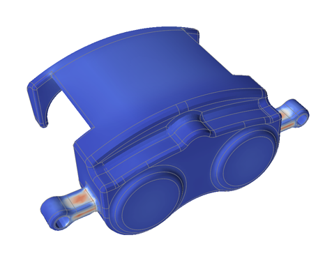
Tension and Compression
The tension and compression result type shows which areas of the model are in tension and which are in compression. These results are derived from the signed von Mises stress results.
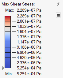
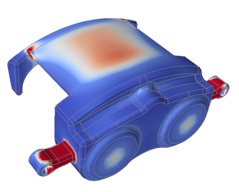
Maximum Shear Stress
The results in the Analysis Explorer include several stress types including maximum shear stress. These stress results can be used in various failure theories to predict part performance and durability.
By default, areas shown in red have exceeded the peak stress, which is the highest
displayed stress for the selected load case. To change the top number in the legend to
the yield stress for a material in the model, click the ![]() icon next to the results slider in the Analysis Explorer.
You can also click on the top number and define a custom value.
icon next to the results slider in the Analysis Explorer.
You can also click on the top number and define a custom value.
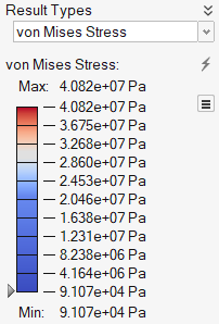
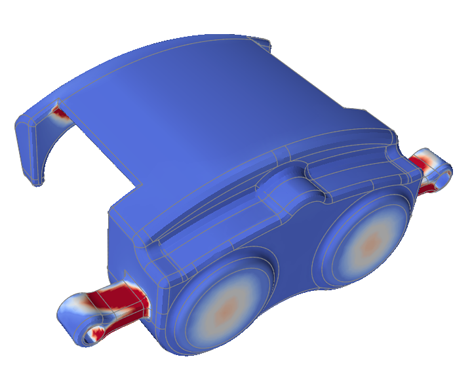
von Mises Stress
The results in the Analysis Explorer include several stress types including von Mises stress. These stress results can be used in various failure theories to predict part performance and durability.
By default, areas shown in red have exceeded the peak stress, which is the highest
displayed stress for the selected load case. To change the top number in the legend to
the yield stress for a material in the model, click the ![]() icon next to the results slider in
the Analysis Explorer. You can also click on the top number and define a custom
value.
icon next to the results slider in
the Analysis Explorer. You can also click on the top number and define a custom
value.
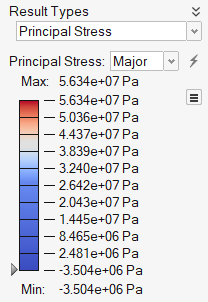
Principal Stress
The results in the Analysis Explorer include several stress types including major and minor principal stress. These stress results can be used in various failure theories to predict part performance and durability.
By default, areas shown in red have exceeded the peak stress, which is the highest
displayed stress for the selected load case. To change the top number in the legend to
the yield stress for a material in the model, click the ![]() icon next to the results slider in the Analysis Explorer.
You can also click on the top number and define a custom value.
icon next to the results slider in the Analysis Explorer.
You can also click on the top number and define a custom value.
Contact (results)
The contact result type allows you to view contact gap, status, and pressure to ensure that the contact is behaving appropriately. It also extracts contact force results for normal, tangential, and traction forces.
A typical use case would be reviewing the contact pressure over the gasket area in a pipe flange to ensure that the gasket doesn't leak.
- There are contacts in the model that have been defined as contacting (as opposed to bonded).
- The linear static analysis was run with the Sliding with Separation option selected.
If these conditions are met, then a contact analysis is automatically run as part of the overall analysis and appears as a result type in the Analysis Explorer.
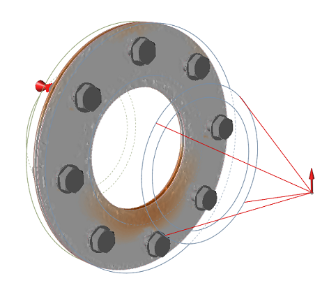
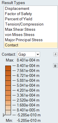 Figure 1. Example 1: Contact Gap Result
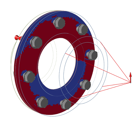
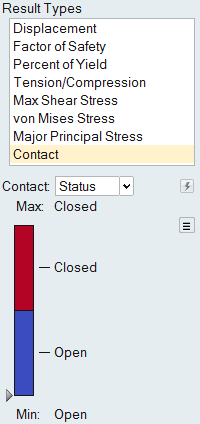 Figure 2. Example 2: Contact Status Result
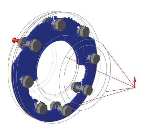
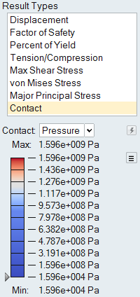 Figure 3. Example 3: Contact Pressure Result