Tutorial: Joints, Motors, and Plotting
Create and modify joints, add angle and speed motors, then run a motion analysis and plot the results.
In this lesson you will learn how to:
- Ground a part
- Connect parts with joints
- Modify the joint state
- Add angle and speed motors
- Run a motion analysis
- Plot motion results
Open the CAD model
-
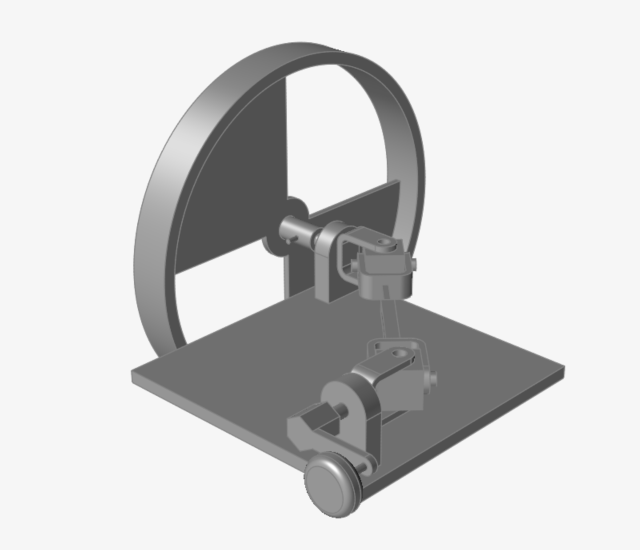
Double-click the M10_DoubleUnivJoint.x_t file in the
Motion folder to load it in the modeling window.
Ground a Part
-
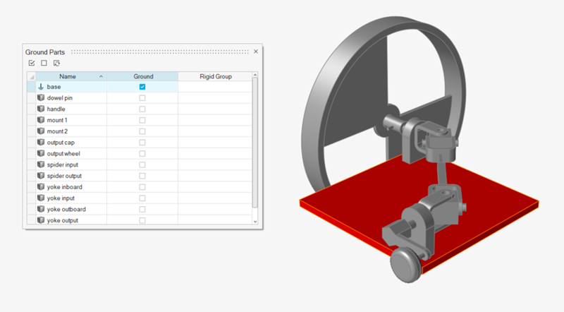
Hover over the Ground tool and click the satellite icon
to open the Ground Parts table.

-
Select the Ground check box in the table for the Base
part to ground it.
The part turns red, indicating that it is a ground part.
Connect Parts with Joints and Modify Joint State(s)
-
Select the Joints tool.

The guide bar appears with default settings (All, Auto).
-
Click the
 button on the guide bar.
Notice that joints are created at neighboring parts in the model, with colors used to indicate the joint state.
button on the guide bar.
Notice that joints are created at neighboring parts in the model, with colors used to indicate the joint state.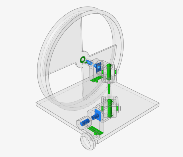
-
Select the blue hinge Joint 6 located at the Mount 1 and
Yoke part connection near the input crank.
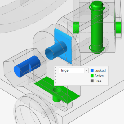
-
In the microdialog, change the joint state from Locked to
Active.
This will allow the yoke shaft to spin inside its mating hole on the mount.

-
Select the blue hinge Joint 12 located at the Mount 2
and Yoke part connection near the output wheel.
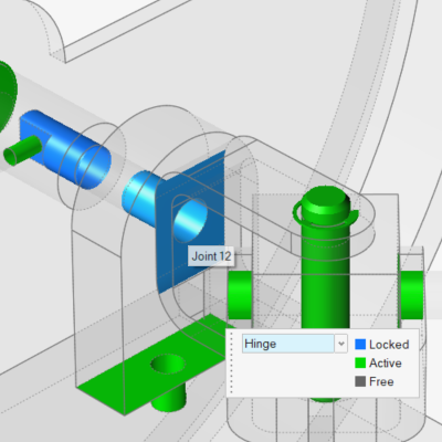
-
Again, change the joint state from Locked to
Active.
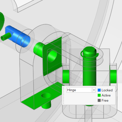
-
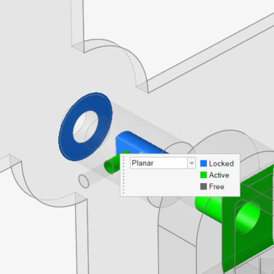
Click on the green planar Joint 10 located at the part
connection between the Output Wheel and the Output Cap.
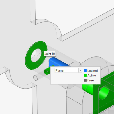
-
This time, change the joint state from Active to
Locked.
Add Angle Motor(s) to Control Part Angles
-
Select the Motors tool.

-
Rotate the model to see the underside of the Base part.
-
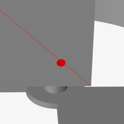
For the first connection, click the Cen (center) snap point on the circular
face of the Mount 1 part.
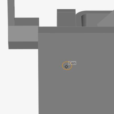
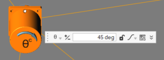
The selected feature turns red. This is the shaft connection point.
-
Click on the Base part.
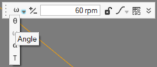
This is the base connection for the motor.A motor appears and the microdialog has the default setting of being a speed motor.
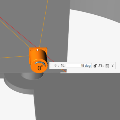
-
In the microdialog, change the motor Type from Speed to
Angle.
-
Notice that the magnitude field now contains 45 degrees as the default
angle.

-
Click the +/- button to reverse the direction of the
motor's rotation.
-
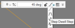
Change the Profile Function to Step Dwell
Step.
-
Pan the model over to the other end of the Base part and click the Cen (center)
snap point on the circular face of the Mount 2 part.
-
Click on the Base part.
Another motor appears, with the same settings as the first motor.
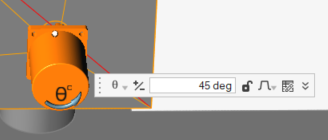
-
Click the +/- button to reverse the motor's direction
of rotation.
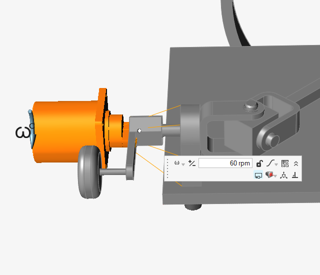
Create a Speed Motor to Drive the Mechanism
-
While the Motors tool is still active, click the Cen (center) snap point on the
face of the handle part.
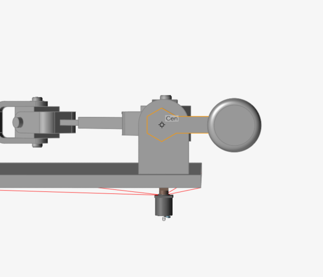
-
Click on the Mount 1 part to create the motor.
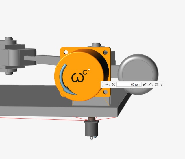
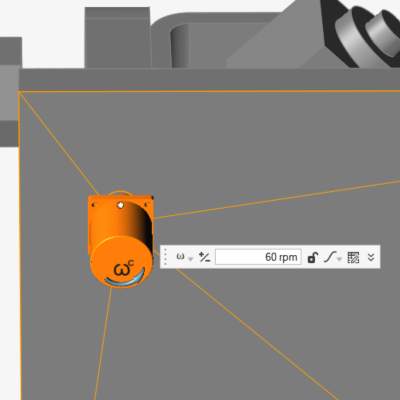
-
In the microdialog, make sure the motor Type is set to
Speed.

-
Make sure the Profile is set to
Step in the microdialog.

-
Click on the chevron in the microdialog to open the advanced motor
options.
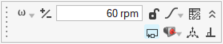
-
Click the
 icon to open the Move
tool.
icon to open the Move
tool.
-
Move the motor away from the handle, offsetting it in the Z direction (the
global -X direction).
Run a Motion Analysis to View Mechanism Behavior
-
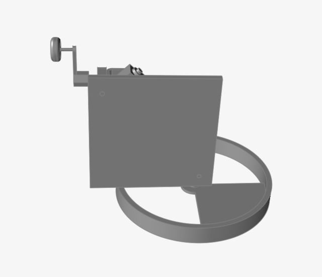
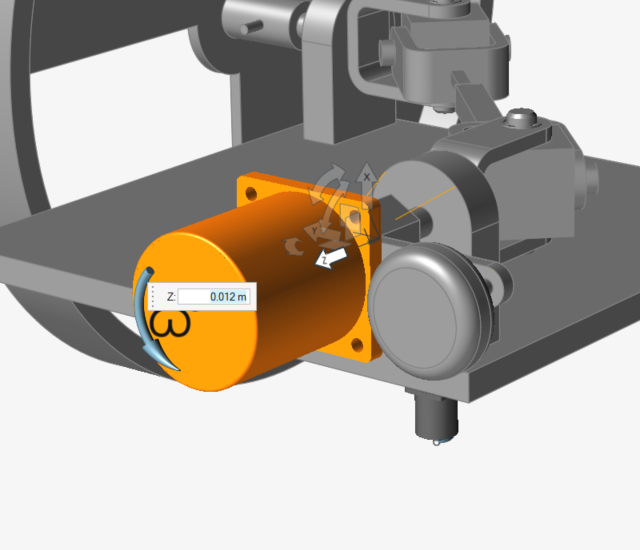
Position the model as shown below.
-
Click the Quick Run button on the Analyze Motion icon to
see the model in motion.
Notice that the ground parts remain stationary and some of the unconnected parts fall down due to the effect of gravity.

-
Click the Quick Run button again to stop the analysis
(if it is still running).

-
Double-right-click, or click the Review Motion Results
icon to exit review mode.

Modify the Angle Motors Using the Motors Table
-
Rotate the model to view the underside of the Base part again.
-
Hover over the Motors icon, then click the
List Motors tool to open the Motors table.

-
Change the angle Value for Motor 2 to 5
deg.

Perform a Motion Analysis and Plot Results
-
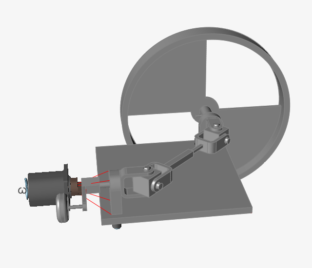
Position the model as shown below.
-
Click the Quick Run button on the Analyze Motion icon to
run the new motion analysis with the first angle motor being locked and the
second angle motor rotating 5 degrees.
-
Click the Quick Run button again to stop the analysis
(if it is still running).
-
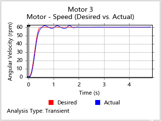
Right-click on the plot and select Speed (Desired vs.
Actual).
Notice that there is some oscillation due to the controller being unable to meet the desired speed perfectly.
Disable the Controller on the Speed Motor
-
Double-click on Motor 3 in the graphics window to edit
it.
-
Deselect the
 icon in the microdialog to disable the
controller.
icon in the microdialog to disable the
controller.
Rerun the Analysis and Review Results
-
Click the Quick Run button to analyze the mechanism with
the controller disabled. Click the stop button to stop the analysis.
-
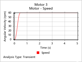
Select Motor 3 to plot the results.
Notice that the desired speed matches the target speed and the oscillations seen previously with the controller are no longer present.
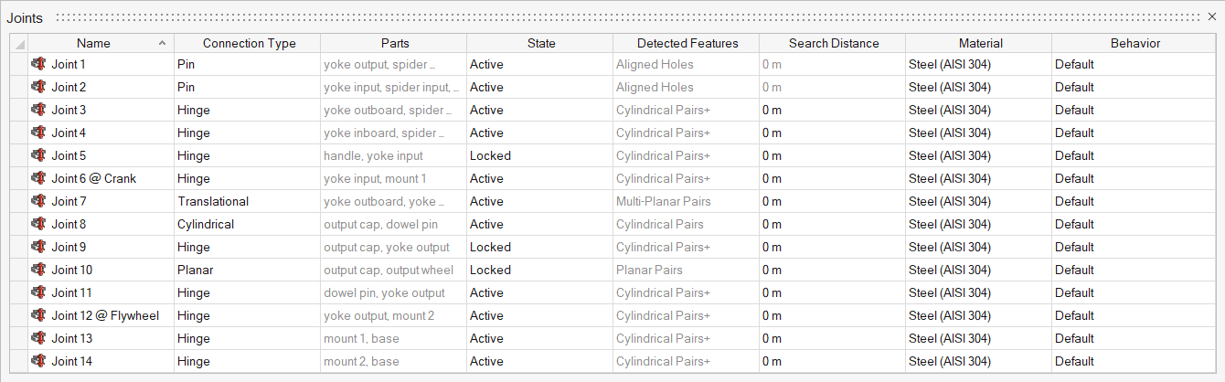
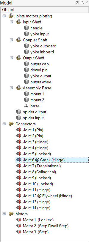
Rename Joints and Plot Results
-
Click the List Joints tool on the Joints icon.

-
Select Joint 12 in the table, then double-click to
rename it Joint 12 @ Flywheel.
-
Select the Review Motion Results tool on the the Analyze
Motion icon.
-
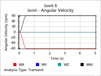
Press the F2 button to open the Model Browser and select
the Joint 6 @ Crank.
-
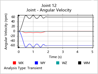
Right-click on the plot that appears and click Angular
Velocity.
Notice that the curves for input shaft velocity are smooth.
-
Select Joint 12 @ Flywheel in the Model Browser and view
the plot.
Notice that the curves for output shaft velocity have oscillations, as expected, due to the 5 degree angle being imposed at Mount 2.