Coupling
The Coupling submenu is available under the Output menu when the current simulation is a Coupling or MIMO simulation. This menu allows the user to configure the passive antennas of the simulation by adding individual antennas or creating arrays of passive antennas. The available options under the Coupling submenu are shown in the following figure:
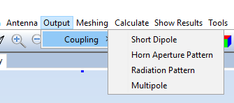
Figure 1. Coupling submenu
If the user selects the Short Dipole option, the following panel is shown:
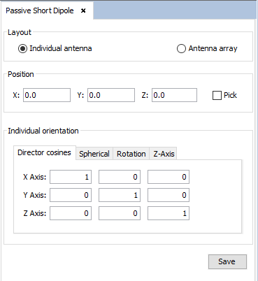
Figure 2. Passive short dipole panel
The user is able to select whether they want to add an individual short dipole or an array of short dipoles. In the first case, the user needs only to specify its location and orientation. In the second case, however, the user will need to specify the following parameters:
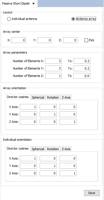
Figure 3. Passive short dipole panel (array layout)
- Array center The Cartesian coordinates of the geometrical center of the array.
- Array parameters The "Number of elements" determine the number of elements of the array in each of the Cartesian axes. The "Tx", "Ty" and "Tz" determine the spacing between two consecutive antennas along each axis.
- Array orientation Determines the axes used to calculate the position of each antenna in the array. This parameter does not affect the rotation of the individual antennas.
- Individual orientation Determines the rotation of each antenna in the array.
If the user selects the Horn Aperture Pattern option in the Coupling submenu, the following panel will appear. Note it is required to import at least one DIA file before adding an antenna of this type.
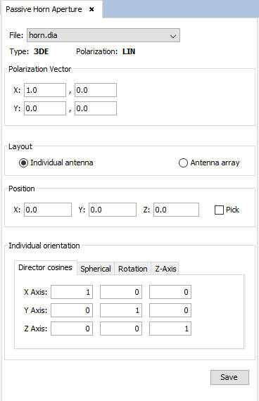
Figure 4. Passive horn aperture panel
In this panel, the user needs to select the DIA (radiation pattern) file to be used for the antenna feeding and set its polarization vector (given by the real and imaginary parts along each coordinate). When the user selects a DIA file, the type and polarization of the radiation pattern file will be shown.
As with the "Short Dipole" antenna type, the user can add arrays of horn aperture antennas. The parameters needed to configure an array of this type of antennas are the same as in the short dipole case.
When the Radiation Pattern option in the Coupling submenu is selected, the following panel will be shown:
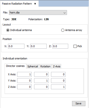
Figure 5. Passive radiation pattern panel
In this panel, the user will need to select the DIA file to be used for the antenna feeding. Like the Horn Aperture Pattern type, the user needs to import at least one DIA file to be able to select this option. Creation of antenna arrays is also possible and the parameters needed to create an arrays are the same as in the previous cases.
If the Multipole option in the Coupling submenu is selected, the following panel will be shown:
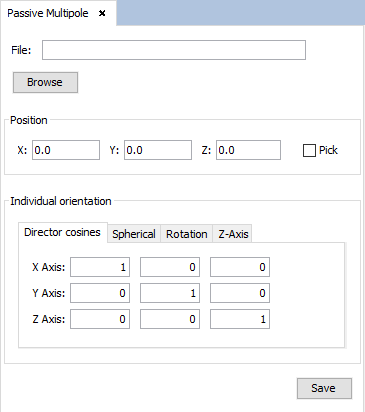
Figure 6. Passive multipole panel
In this panel, the user needs to select the SUJ file that contains the multipole definition. Unlike the previous antenna types, it is not possible to create arrays of passive multipole antennas.
When the user has finished adding and configuring an antenna or array of antennas, they need to press the "Save" button to confirm the changes. If all the information is correct, the created antennas will be shown on the screen, represented by magenta cones.
The user can add multiple passive antennas, as long as all the antennas are of the same type. This means that only one kind of passive antenna can be configured in a project at a given time. To change the passive antenna type, the user only needs to add an antenna of the type they want to use. If, when doing this, one or more passive antennas of a different type have been added before, the application will warn the user that those antennas will be deleted before adding the new passive antenna:
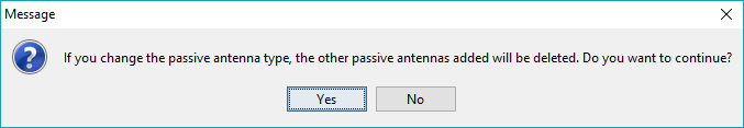
Figure 7. Warning when adding passive antennas of a different type
Pressing "Yes" will confirm the addition of the new antenna and therefore, the deletion of the previous passive antennas. Otherwise, the previous antennas will not be deleted and the creation of the new antenna will be aborted.
The currently configured type of passive antenna will be marked with a green tick next to the corresponding option in the Coupling submenu, as shown in the next image:
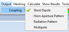
Figure 8. Green tick showing the current type of passive antenna