View Ray
This option allows the user to view the rays emitted by the active antennas in the simulation.
This command plots the rays emitted by the active antennas in the simulation only if the check box Output Ray-Tracing in the Simulation panel has been selected.
When initially open, the panel will display the rays for a particular step, order, antenna and observation point or direction. All the effects type are selected by default. The user can change:
- Ray effect
- it is possible to select one of these options (direct, reflected, transmitted, creeping and diffracted) or all of them.
- Ray selection
-
- Order the parametric step to select. These should have been defined prior to the calculation when designing the simulation.
- Antenna select one of the antennas that were previously added to the project.
- Point/Theta phi select a particular observation point or direction.
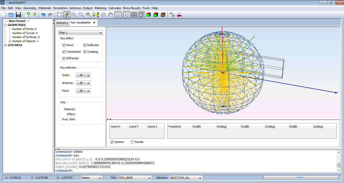
Figure 1. Ray visualization panel
Selecting a ray will highlight it in yellow color and its information will be shown in the Info panel (length of the ray, type of effect and propagation time) at the bottom. This information is composed of frequency and the modulus and argument for each of its components.
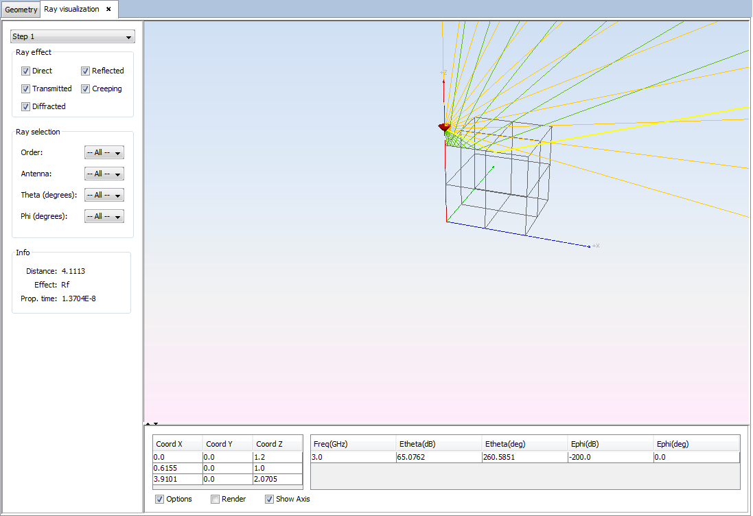
Figure 2. Ray information