Create Mesh
The most common parameters for the meshing process may be edited in this window.

Figure 1. Meshing panel
The following parameters may be edited:
- Divisions per wavelength This section specifies the size of the
elements to be generated in the meshing process. Let c be the
speed of light in the vacuum (meters per second), given a number of divisions
D and a frequency f, the size of the
generated elements L is given by: L = lambda / D ;
lambda = c / f The larger is the number of divisions specified the
denser are the generated meshes. Different meshing resolution is considered for
planar and curved surfaces. Also, a specific number of divisions may be assigned to
different used by using the Specify Divisions option within
the Advanced Options section.
- Planar surfaces To set the number of divisions to be applied on planar surfaces which are contained in a single plane.
- Curved surfaces To set the number of divisions to be applied on curved surfaces which are not contained in a single plane.
- Mesh Mode This section specifies how the meshing frequencies are
assigned. It allows considering different frequencies in the meshing process than the
specified in Simulation parameters section.
- Octaves When a frequency swept is enabled, the meshing frequencies are different to the simulation ones. An automatic frequency range per octaves is performed, that depends on the Initial frequency, the Final frequency set in the Simulation parameters panel, and the number of Bands per octave specified. The higher is this parameter, the more frequencies are considered for the meshing process.
- Frequency Select this option to set the desired Frequency for the meshing process, in GHz. If a Frequency Sweep has been enabled within the Simulation parameters panel, all the steps in the sweep will consider the mesh generated at the Frequency value.
- All frequencies: a meshing by each frequency is built, so it is the more accurate option. This option will only be chosen when the user needs a very accurate mesh.
- Processors To set the number of processors used in the meshing process.
- More Options:
- Mesh Repair Select this option to evaluate and repair the generated mesh. It is recommended for analyzing complex geometries, especially whenever a good convergence is not achieved. Several problems will be studied and solved isolated and spurious elements are removed, and overlapped regions are repaired. The detection of this defects on the mesh depends on two parameters that are explained below and can be edited by clicking on Options button. Elements with smaller area than the minimum allowed, isolated elements or parallel elements closer than a minimum distance are deleted from the output mesh. The minimum area and distance depend on the wavelength, the number of divisions per wavelength selected, and the Area and Border factors, and they are determined as:
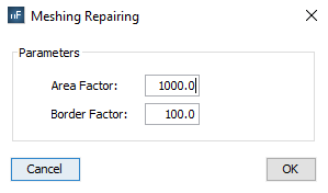
Figure 2. Meshing Repairing options
- Click on Advanced Settings button to edit more complex meshing parameters. The available options are detailed in next subsection.
- Mesh click on this button to save the parameters and start the meshing process.