Simulation Case Editor
The Simulation Case Editor allows the user to manage the list of simulation cases of the project, as well as changing the parameters of already existing simulation cases.
The Simulation Case Editor consists on two different tabs:
- Refraction Profiles This tab allows the user to create and edit the refraction profiles that will be used in the simulation case. A refraction profile specifies how the refraction index of the air varies along with the height.
- Case Definition This tab allows the user to configure the numerical parameters of the simulation case, such as the parameters of the antenna and the spatial bounds of the simulation. In this tab, the user also needs to set the topographic profile used for the simulation case, as well as the assignation of the refraction profiles created in the previous tab to the different range values.
In addition, the top of the Simulation Cases Editor (shown in the next figures of this section) allows the user to create new simulation cases or delete already existing ones. The combobox located at the top of the panel allows the selection of the simulation cases that is going to be edited, and whose contents are shown in the Simulation Cases Editor. When the user finishes the edition of the parameters of the simulation case, they need to press the "Save Simulation Case" button located on the bottom of the panel.
The options in each of the tabs of the Simulation Cases Editor will be explained next.
Refraction Profiles Tab
The contents of this tab are shown in the following figure:
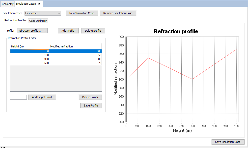
Figure 1. Refraction Profiles Tab of the Simulation Case Editor
In this tab, it is possible to manage the list of refraction profiles contained in the simulation case. Therefore, it is possible to create new profiles and delete the selected profile. When selecting a refraction profile in the combobox, the table will show the points of the refraction profile, each composed of the height (in meters) and the modified refraction (M).
It is possible to add new points to the refraction profile by entering the height value in the field next to the "Add Height Point" button and then pressing this same button. The points of the refraction profile will be ordered in the table by height value. The chart on the right will be updated automatically to represent the values of the refraction points of the table.
When the user has finished editing the points of the refraction profile, they must press the "Save Profile" button to confirm the changes.
Case Definition Tab
The contents of this tab are shown in the following figure:
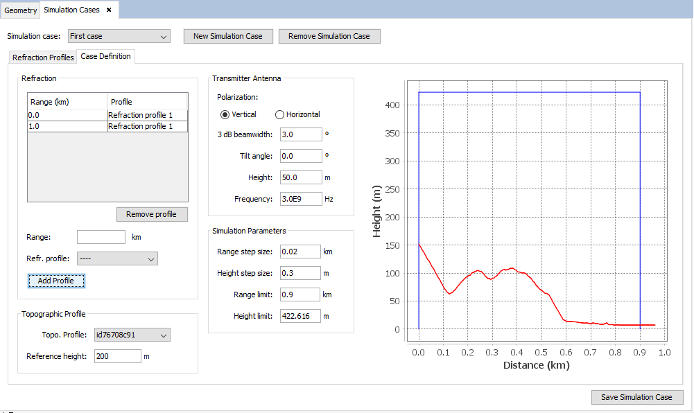
Figure 2. Case Definition Tab of the Simulation Case Editor
This tab allows the user to define the parameters of the simulation case:
- The Refraction panel allows the user to specify the refraction profiles that will be used in the simulation case. Each refraction profile is assigned a range, which is the distance from the origin the profile will take effect at. It is recommended to assign refraction profiles to ranges so that the refraction profiles span the whole range interval of the simulation (from 0.0 to the value specified in the "Range limit" field). To add a refraction profile, the user needs to enter the range in the "Range" field (in km), select the refraction profile in the drop-down list just below and press the "Add Profile" button.
- The Topographic Profile panel allows the user to specify the topographic profile used for the simulation (depicted in red on the chart on the right side). The "Reference Height" panel allows the user to shift the Z-coordinate (or height coordinate), so that height 0 will be located in another height value. It is recommended to set this value to be close to (but not greater than) the minimum height of the topographic profile used.
- The Transmitter Antenna panel allows the user to specify the parameters of the antenna of the simulation (the antenna will always be located at range = 0). The parameters that can be setup are the polarization of the antenna, the half power beamwidth angle, the height (above the terrain at range = 0) and the frequency.
- The Simulation Parameters panel contains the parameters of the SSPE (Split-Step Parabolic Equation) algorithm. On the one hand, it allows to specify the range and height increments that the algorithm will use to compute the fields. On the other hand, it allows to specify the computational domain of the simulation with the "Range limit" and "Height limit" fields. These bounds are depicted in blue on the chart.