Example 2
In this example, the bistatic RCS of a flare is calculated using a frequency sweep from 0.4 GHz to 0.6 GHz (400 MHz to 600 MHz).
Step 1
Create a new project using Step 1 to Step 5 discussed in Example 1.
Step 2
Click on Geometry → Solid → Flare.
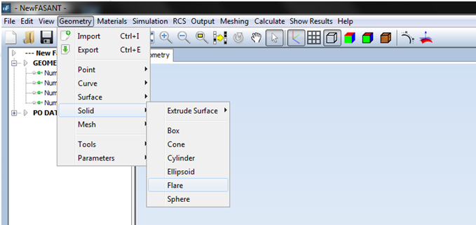
Figure 1. Create flare command
Step 3
Enter the following parameters to define the flare in the command line as shown in the next Figure:
· First corner of base [x y z] -0.5 -1 0
· Base size [width depth] 1 2
· Height 2
· First corner of top [x y] -0.25 -0.25
· Top size [width depth] 0.5 0.5
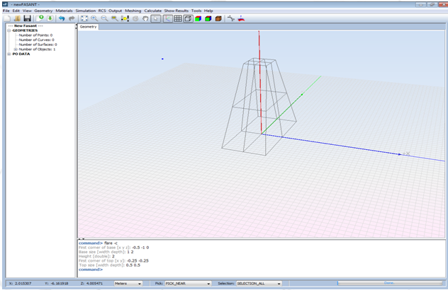
Figure 2. Flare Parameters box
Step 4
Select Simulation → Parameters. Select 1 bounce (simple reflection), and define the diffraction and a frequency sweep from 0.4E9 Hz to 0.6E9 Hz (400 MHz to 600 MHz) as shown in the next Figure, and left-click on Save button.
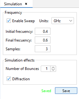
Figure 3. Simulation Parameters panel
Step 5
Select RCS → Parameters. Define the parameters as shown in the following Figure, and left-click the Save button.
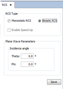
Figure 4. RCS Parameters panel
Step 6
Select Output and left-click on Observation directions. Define the parameters as shown in the next Figure, and left-click the Save button.
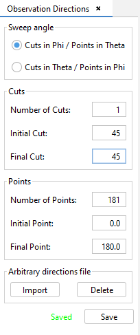
Figure 5. Observation Directions panel
Step 7
Select Meshing → Create Mesh. Define the parameters as shown in the next Figure, and left-click the Mesh button.
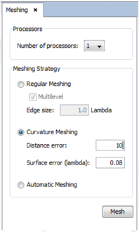
Figure 6. Mesh process
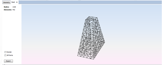
Figure 7. Mesh process
Step 8
Then select Calculate → Execute and enter the number of processors to be used in this simulation.
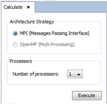
Figure 8. Execute Parameters panel
Step 9
Select Show Results → Far Field → View Cuts.
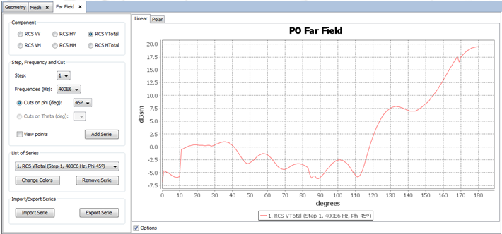
Figure 9. RCS Graphic
Step 10
Select Show Results → Far Field → View Text Files.
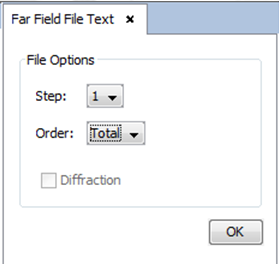
Figure 10. Text Files panel
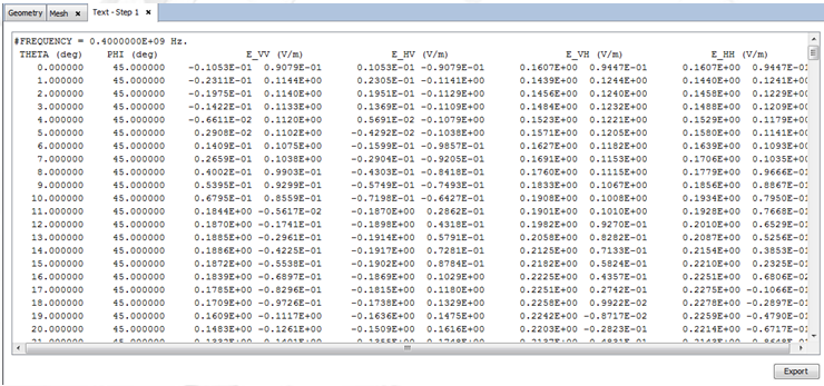
Figure 11. Result Text File visualization
Step 11
Select Materials → Add to add a new material to the simulation in the new panel shown at the right side of the window.
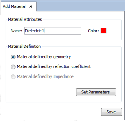
Figure 12. Add Material Parameters box
Then select the “Material defined by Geometry” option and also left-click the “Set Parameters” button to define the material properties as shown in the next Figure. Press Save.
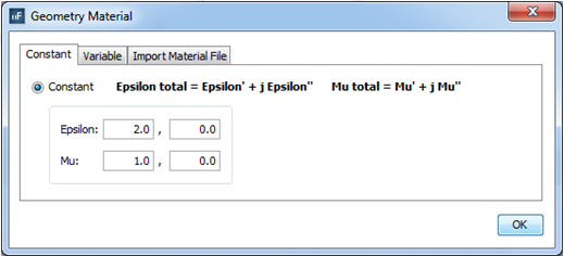
Figure 13. Material defined by geometry Properties box
Step 12
Select Material → Assign to assign the new material properties to the geometry. Select the object and left-click the “Assign” button as shown in the next Figure.
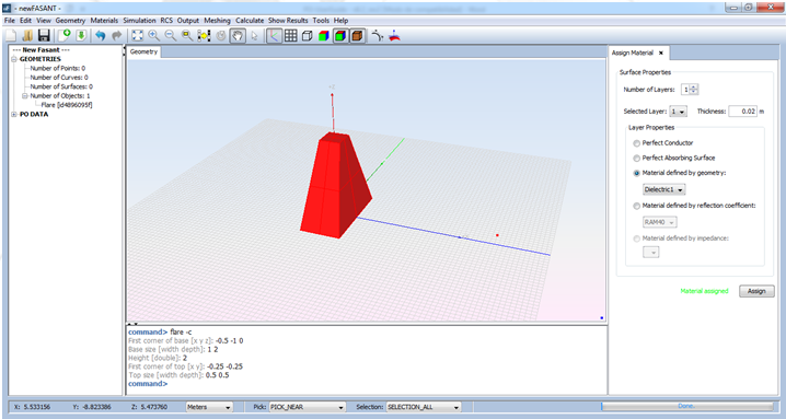
Figure 14. Material Assign object selection
Step13
Re-mesh the geometry and run the simulation again. Then open the new RCS results shown in the next Figure.
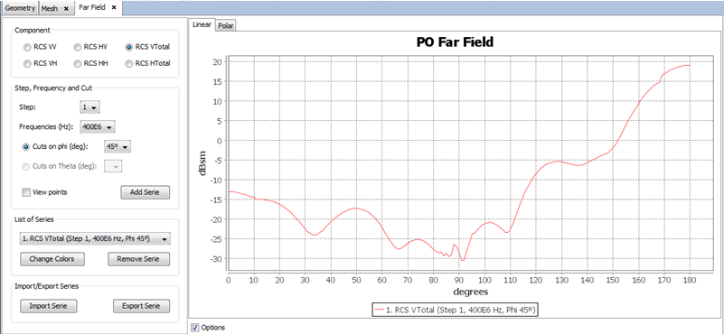
Figure 15. RCS Graphic