Import displacements from a .csv file and map onto
spots.
Purpose
SimSolid performs meshless structural
analysis that works on full featured parts and assemblies, is tolerant of
geometric imperfections, and runs in seconds to minutes. In this tutorial,
you will do the following:
Import .csv file with translation and
rotation data and map the data on spots created on the fly at
specified locations.
.csv import and
mapping of loads from traditional FE solvers to SimSolid facilitates interoperability
with other products.
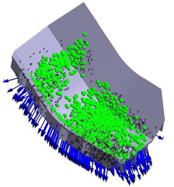
Model Description
The following model files are needed for this tutorial:
ImportDisplacementsOnSpot.ssp
ImportSpotDisplacement.csv
Figure 1.
This file has the following specifications:
Material is set to Steel for all parts.
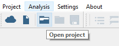
Open Project
Start a new SimSolid session.
Click the (Open Project) icon.
Figure 2.
In the Open project file dialog, choose
ImportDisplacementsOnSpot.ssp
Click OK.
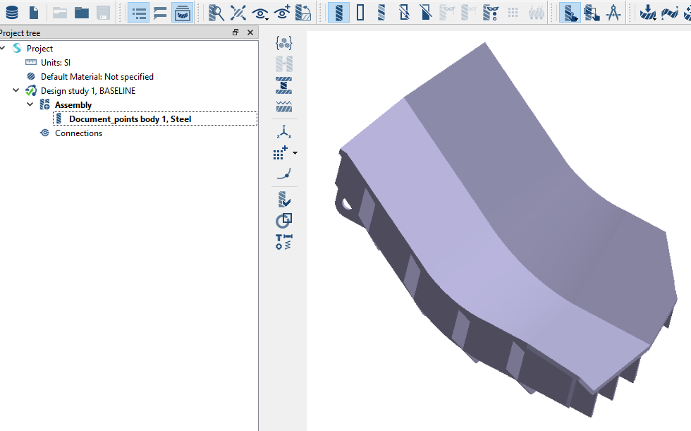
Review Model
In the Project Tree and modeling window, review the model.
Ensure all project specifications are included.
Figure 3.
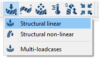
Create Structural Linear Analysis
On the main window toolbar, click (Structural analysis).
Choose Structural linear.
Figure 4.
The new analysis appears in the Project Tree under
Design study 1 and the Analysis Workbench
opens.
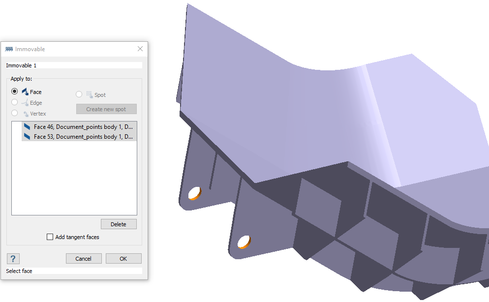
Create Immovable Support
In the Analysis Workbench, click (Immovable support).
In the dialog, verify the Faces radio button is
selected.
In the modeling window, select the faces highlighted in
Figure 5.
Figure 5.
Click OK.
The new constraint, Immovable 1, appears in the Project Tree. A visual representation of the constraint is
shown on the model.
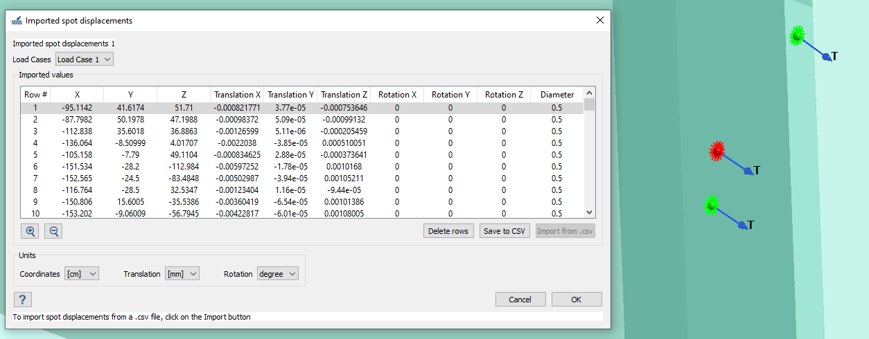
Import Spot Displacements
On the workbench toolbar, select > Import spot displacements.
Set the coordinate units to cm and translation to
mm.
Spot diameter uses the same units as coordinates.
In the Imported spot displacements 1 dialog, click
Import from .csv.
Select ImportSpotDisplacement.csv from the file explorer
and click Open.
The imported displacements are shown in the dialog and mapped on the
spots created with 0.5 cm diameter in the modeling window. You can edit the values in the dialog to change the load location, value,
and spot diameter.
Review the loads in the dialog and click OK to accept.
Figure 6.
Run Analysis
In the Project Tree, open
the Analysis Workbench.
Click (Solve).
Review Results
In the Project Tree, select the analysis results
branch.
On the Analysis Workbench toolbar, select (Result plot) > Displacement > Displacement Magnitude.
 (Open Project) icon.
 (Structural analysis).
 (Immovable support).
 > Import spot displacements.
 (Solve).
 (Result plot) > Displacement > Displacement Magnitude.
